From the Connectivity tab on the Contacts panel, the bodies/graphics involved in contact can be defined, as well as checks on graphics for suitability for contacts can be performed.
Contacts panel - Connectivity tab - 3D Rigid to Rigid Contact
Body I
|
Select the first body to define contact.
|
Body J
|
Select the second body to define contact.
|
|
Graphic
|
For each of the selected bodies, choose the graphics that are involved in the contact from the graphics in the list below the body.
All eligible graphics on a body are automatically selected for contacts. Individual graphics may be selected/deselected by using the individual check box located next to each graphic entity in the list.
Alternately, you can click on the Graphic collector  to activate it and then simply select the desired geometry from the graphics window. to activate it and then simply select the desired geometry from the graphics window.
The All  , None , None  , and Reverse , and Reverse  options (located below the Graphic collector) are also provided to allow you to quickly select the set of graphics that you would like to use for the contact. options (located below the Graphic collector) are also provided to allow you to quickly select the set of graphics that you would like to use for the contact.
|
|
Material inside
|
This flag specifies if the graphic has material inside the volume or outside.
When this option is selected, it means the selected geometry is solid. In other words, it is filled with material and its exterior is devoid of material. Consequently, the surface normals of the geometry point outward.
When the option is not selected, it means the converse is true: the exterior of the geometry is filled with material and the interior is devoid of material. In this case, the surface normals of the geometry point inward.
This flag is useful for reversing the surface normals of a geometry for contact simulations.
|
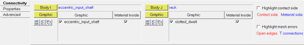
Highlight contact side
|
Activate this option to visualize the direction of the contact of the surface mesh. The side of the surface that would be in contact is indicated by a red color, while the material side is indicated by a blue color.
|
Highlight mesh errors
|
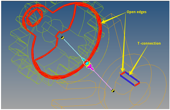
Activate this option to visualize any discontinuities in the surface mesh, such as open edges and T-connections. An open edge is highlighted through a red line, while a T-connection is highlighted using a blue line. For better visibility, the visualization of graphic components involved are changed to a non-shaded mode.
Note - If no mesh errors are found, this option will be disabled and will display as No mesh errors.
|
|
|
Note In the ADAMS SolverMode, if the graphic defined is a File type graphic - it will require an additional parasolid file.
Comments
MotionSolve has following requirements for a robust 3D contact simulation:
| 1. | The individual graphics involved in contact should form a closed volume. In other words, the graphic mesh should not have any open edges or T-connections. Use the Highlight mesh errors option to check for open edges and T-connections. |
| 2. | The normal of the mesh should point in the direction of contact. The side of the surface mesh, when seen such that the normal direction points towards the viewer is the contact side. If viewed from the opposite direction, it is referred to as the material side. Use the Material Inside and Highlight contact side options in the panel to set the correct direction of contact. |
Below is an example of how the Material Inside and Highlight contact side options work:
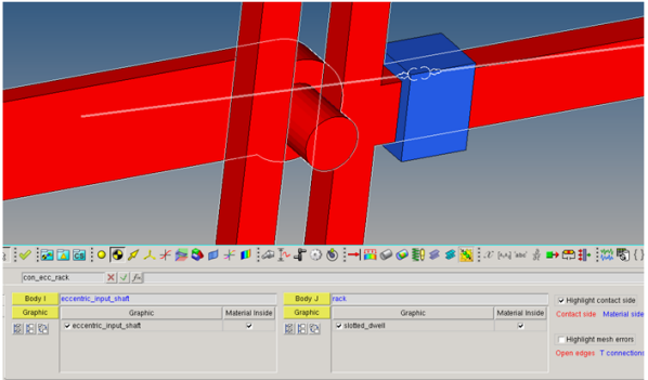
With both of the graphics having the Material Inside option activated, checking the Highlight contact side option will display the color for both of these graphics in red when viewed from the outside of the graphics.
In certain cases, if the contact direction is on the reverse, the Material Inside flag can be flipped.
Refer to Best Practices for Running 3D Contact Models in MotionSolve to understand more about building models for successful contact simulation.
See Also:
Graphics Panel
*Contact() (MDL Statement)


