This section describes the Curve to Curve (CVCV) Joint entity of MotionView and shows the various usage, creation, and editing methods.
Theory/Background
The Curve to Curve Joint defines higher pair constraint. The constraint consists of a 3D curve fixed on one body rolling and sliding on a 3D curve fixed on a second body. The curves are required to have a unique point of contact and a common tangent at that point of contact. The curve-to-curve constraint is useful for modeling cams where the point of contact between two parts changes during the motion of the system. The curves always maintain contact, however, even when the physics of the model might dictate that one curve lift off the other.
The curve-curve constraint removes three degrees of freedom from the system. One constraint enforces that the tangents to the two curves at the point of contact always remain parallel. This constraint prevents the bodies from spinning relative to each other about any axis normal to the common tangent at the point of contact. The other two constraints prohibit translational motion in the plane normal to the common tangent at the point of contact.
Common Applications of CVCV Joints are:
| • | Cam Follower Mechanisms (when there is a chance of a varying point of contact instead of a single point contact) |
| • | Non-Planar 3D Track Simulations |
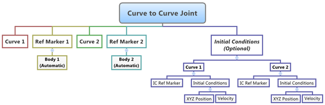
The topological information required to define an CVCV Joint is shown in the figure below:
Entity Data Members
The data members of the CVCV Joint can be classified into the following members:
Connectivity
An CVCV Joint needs the following:
| • | Two Bodies – Body 1 and Body 2 |
| • | Two Curves – Curve 1 and Curve 2 (each belonging to respective bodies) |
| • | Two Reference Markers – Ref Marker 1 and Ref Marker 2 (each belonging to respective bodies which also represent the coordinate systems that the curves are defined in) |
This advanced joint can only be modeled as a Single entity (it cannot be modeled as a Pair entity).
Properties
The CVCV Joint can have two types of Initial Conditions – Position and Velocity.
| • | Both curves of the CVCV Joint need to have initial contact points defined. If user-defined contact points are not provided, MotionView will measure the distance between all the points on the curves and pick two points (one for each curve) that are close to each other. You can optionally specify the two contact points by activating the Use XYZ option. |
| • | The sliding velocity at the contact points can also be optionally specified. This velocity is as measured by an observer located at Ref Markers of each curve. You can specify this velocity by activating the Use Velocity option for both curves. |
| • | Additionally a unique Reference Marker can be specified for the Position and Velocity initial conditions of each curve. By default, this marker is the curve Reference Marker that belongs to Body 1 and Body 2 respectively. This can be specified by activating the Use Initial Condition Marker check box. |
If the values for the Initial Contact Point and Initial Contact Velocity are known for the CVCV joint, then it is recommended that they are specified while defining the joint.
Creating and Editing Joints
To learn how to add a Curve to Curve Joint to a model, please see the Joints topic.
Important Note - In order to completely specify a CVDV Joint, the following entities must first be created:
| 1. | Two 2D or a 3D reference curve entities created using the Curves panel. |
| 2. | Two Markers that belongs to Body 2 and Body 2 of the Joint and Located appropriately so that the Curves entity can be meaningfully described as belonging to the Coordinate System of the Reference Markers. |
| 1. | Once an CVCV Joint has been added to the model using any of the "entity" creation methods, the panel for the joint will automatically be displayed in the panel area. See the panel example below: |
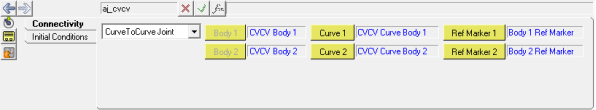
Joints Panel (CVCV Joint) – Connectivity Tab
| 2. | In order to complete the joint definition, four entities need to be specified: |
| - | Double-click on the Curve 1 collector and pick the curve that belongs to Body 1. In the same way, pick the curve for Curve 2 that belongs to Body 2. |
| - | Click on the Ref Marker 1 button and pick the Reference Marker that belongs to the Body 1. In the same way, click the Ref Marker 2 collector and pick the Reference Marker that belongs to Body 2. |
| - | The fields of Body 1 and Body 2 will automatically get populated with the appropriate body labels (as shown in the figure above). |
| 3. | Click on the Initial Conditions tab. The panel will look as shown in the figure below: |
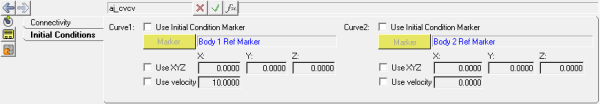
Joints Panel (CVCV Joint) – Initial Conditions Tab
| 4. | For each of the curves of the CVCV Joint there are three optional properties that can be set: |
| - | Initial Contact Points - to set the initial contact point for each curve, activate the Use XYZ check box and type in the initial contact point coordinates. |
| - | Initial Contact Velocities - to set the initial contact velocities for Curve 1 and Curve 2, activate the Use velocity check box and type in the velocity value that is to be used. |
| - | Initial Condition Marker - to change the initial condition marker from the default, activate the Use Initial Condition Marker check box and pick the desired marker for using it as the initial condition reference marker. |
|
| 1. | Left click the Advanced Joints panel icon  on the Constraint toolbar. on the Constraint toolbar. |
The Project Browser will filter the entities and display only the advanced joints in the model.
| 2. | Select the desired joint in the Project Browser. |
The corresponding panel is automatically displayed.
| 3. | From the Connectivity tab, use the Joint type drop-down menu to change the joint type, or use the collectors to change the bodies and other topological/properties of the joint. |
|
Curve to Curve Joint in MDL and XML Formats
The model containing the CVCV Joint can be saved in MDL format from MotionView and exported in the MotionSolve XML format.
Syntax:
*CurveToCurveJoint(cvcv_name, "cvcv_label", body_1,
body_2,
curve_1,
crve_2,
ref_marker_1,
ref_marker_2,
[icm_1],
[icm_2])
Example:
*CurveToCurveJoint( aj_cvcv, "Curve to Curve Joint", b_b1, b_b2, crv_b1curve, crv_curveb2, m_b1rm, m_b2rm, aj_cvcv.rm1, aj_cvcv.rm2 )
To understand the complete syntax of the MDL statement please refer to the *CurveToCurveJoint topic.
|
The *SetJointIC statement can be used for specifying initial conditions for the curve to curve joint.
Syntax:
*SetJointIC(joint_name, ic_x_disp_c1,
ic_y_disp_c1,
ic_z_disp_c1,
ic_vel_c1,
ic_x_disp_c2,
ic_y_disp_c2,
ic_z_disp_c2,
ic_vel_c2)
Example:
*SetJointIC(aj_cvcv, 200.2, 569, 456, 10, 569, 658, 652, 25)
To understand the complete syntax of this MDL statement please refer to the *SetJointIC topic.
|
To learn how to create a complete model using MDL Statements please refer to tutorial MV-1060: Introduction to MDL.
|
The CVCV Joint when exported to the MotionSolve XML format is defined as a Constraint_Joint statement.
Syntax:
<Constraint_CVCV
id = "integer"
label = "Advanced Joint Label"
i_marker_id = "integer"
i_curve_id = "integer"
[i_disp_x0 = "real" ]
[i_disp_y0 = "real" ]
[i_disp_z0 = "real" ]
[i_velo = "real" ]
j_marker_id = "integer"
j_curve_id = "integer"
[j_disp_x0 = "real" ]
[j_disp_y0 = "real" ]
[j_disp_z0 = "real" ]
[j_velo = "real" ]
</Constraint_CVCV>
In case of the CVCV Joint the model statement will be as shown below:
<Constraint_CVCV
id = "301001"
label = "Curve to Curve Joint"
i_marker_id = "30102032"
j_marker_id = "30103021"
is_no_slip = "FALSE"
i_disp_x0 = "200.2"
i_disp_y0 = "569."
i_disp_z0 = "456."
i_vel0 = "10."
j_disp_x0 = "569."
j_disp_y0 = "658."
j_disp_z0 = "652."
j_vel0 = "25."
i_curve_id = "301001"
j_curve_id = "301002"
/>
In the above XML Model statement the i_marker_id and j_marker_id represent the I and J markers of the Joint which belong to Body 1 and Body 2 respectively. To understand the complete syntax of the Constraint_CVCV XML model statement, please refer to the MotionSolve Reference Guide Page for Constraint_CVCV.
|
Creating and Editing Curve to Curve Joints using Tcl
In MotionView, Tcl can be used to add any MDL entities to the model. There are two Tcl commands that can be used to add an entity:
Syntax:
mdlmodel_handle InterpretEntity new_handle keyword varname label
Example:
mdlmodel_handle InterpretEntity advjoint CurveToCurveJoint aj_cvcv "\"Curve to Curve Joint\"" b_b1 b_b2 crv_b1curve crv_curveb2 m_b1rm m_b2rm aj_cvcv.rm1 aj_cvcv.rm2;
|
The initial conditions for the Curve to Curve Joint can be specified using the InterpretSet TCL command.
Syntax:
mdlmodel_handle InterpretSet keyword tokens
Example:
mdlmodel_handle InterpretSet SetJointIC aj_cvcv 200.2 569 456 10 569 658 652 25;
|
The command InterpretEntity is used to add entities to the model and the command InterpretSet is used to set the entity properties. So in the case of the Curve to Curve Joint, the properties that can be set are the Joint Initial Conditions. Extended definitions for InterpretEntity and InterpretSet can be found in the HyperWorks Desktop Reference Guide.
Note - When using the InterpretEntity and InterpretSet commands, it is important to also use the Evaluate command in order for the changes to take effect immediately.
To learn how to create a complete model using Tcl commands, please refer to tutorial MV-1040: Model Building Using Tcl.
See Also:
Advanced Joints Panel
Adding and Removing Entities
*CurveToCurveJoint (MDL Model Statement)
Constraint_CVCV (XML Command)
InterpretEntity (Tcl Command)
InterpretSet (Tcl Command)


