Deformable Bodies - Nodes |

|

|

|

|
|
Deformable Bodies - Nodes |

|

|

|

|
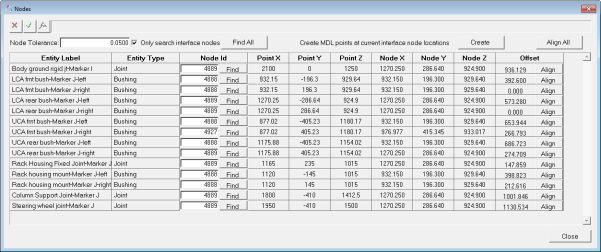
The Nodes button enables you to associate markers defined on the flexible body (including joint, force, markers, etc.) to an interface node on the flexible body.

Deformable Body - Nodes dialog
Based on other entities that reference the body as part of the topology of the model, one line per reference is displayed in the nodes dialog box.
The dialog tabulates:
| • | Marker associated with the flexible body, either explicitly defined or implicit through any other entity such as joints, bushings and forces |
| • | Entity type |
| • | Node ID to be associated with the marker |
| • | Point X, Y, & Z coordinates where the entity origin is located |
| • | Node X, Y, & Z coordinates |
| • | Offset between the point and the associated node |
You can directly enter the interface node IDs or you can use the Find option. When using Find, make sure the desired node is found by MotionView. In addition, verify that the FEA model used to generate the flexible body has nodes in the locations corresponding to the MDL point. The Align button moves the MDL point to be coincident with the referenced interface node. This should be used only when the spatial difference between the interface node and the MDL point is acceptable. Clicking Align affects the geometry of the MDL model.
You can also use the Find All and Align All options to find all of the interface nodes and align the connecting points to interface nodes respectively.
Nodes is available when MotionSolve, ADAMS, or ABAQUS is selected.
See Also: