Introduction
The new 3D contact algorithm in MotionSolve14.0 requires good quality geometry (represented by a triangulated mesh). Following are the requirements for good quality geometry for a robust simulation:
| • | Each component mesh should form a closed volume. This means that the given mesh should not contain any open edges (edge which is part of only one element) or T- connections (two elements join at the common edge in form of a T). |
| • | Mesh should be of uniform size. |
| • | Element surface normal should point in the direction of expected contact. |
Click here to learn more about best modeling practices for a 3D contact simulation.
It is possible that certain CAD component surfaces might lead to faulty geometries such as open edges and T connections. Also, legacy models (MotionView models created prior to version 14.0) might have faulty geometries since the old contact algorithm did not impose any mesh quality requirements.
MotionView along with HyperMesh provide certain simple mesh manipulation tools to fix such faulty geometries.
Mesh Manipulation Tool
The Mesh Manipulation tools are part of the utility tab in HyperMesh when invoked from Import CAD or FE utility in MotionView. To access the tool:
| 1. | Click on Import Geometry toolbar  (Or from the File menu select Import>Geometry). (Or from the File menu select Import>Geometry). |
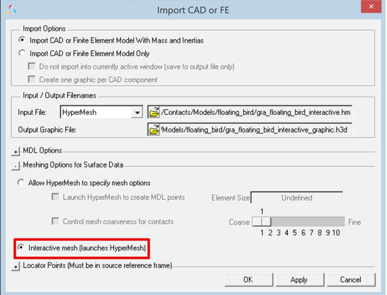
The Import CAD or FE dialog is displayed.
| 2. | After selecting the Input File, turn on the Interactive mesh (launches HyperMesh) radio option. |
| Note | To cleanup the geometry in legacy models, load the relevant graphic H3D in HyperView, export it to the FEM format and use it as the input file in this step. Refer to the Working with legacy graphics section below. |
HyperMesh is launched in the interactive mode, importing the geometry and displaying the Utility tab in the left side browser area. The Utility tab contains Mesh Manipulation tools along with MV Import Options.
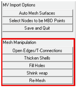
The Mesh Manipulation tool consists of the following utilities:
Open Edges/T-Connections
|
Identifies and removes open edges and T connections.
|
Thicken Shells
|
Add thickness to a shell component and convert it into a closed volume.
|
Fill Holes
|
Remove holes from a component.
|
Shrink wrap
|
Wrap a layer of mesh around an existing mesh.
|
Re-Mesh
|
Re-mesh the component.
|
Open Edges/T-Connections
Open edges are generally formed either due to a mismatch of elements (unequal size) between adjacent surfaces or when the two elements on each adjacent surface don’t share common nodes. In this case, there would be two coincident nodes at the edge forming location. Since the nodes are not shared, the edges belong to only one element each thereby forming open edges.
The Open Edges/T-Connection utility has the following options:
Display Open Edges
|
Highlights open edges on the selected components.
|
Display T-Connections
|
Highlights T-Connections on the selected components.
|
Equivalencing Tolerance
|
Specify a tolerance value to equivalence nodes.
|
Equivalence
|
Equivalence nodes within the specified tolerance value.
|
Reject
|
Rejects the operation.
|
Accept and Close
|
Accepts the performed operation and closes the utility.
|
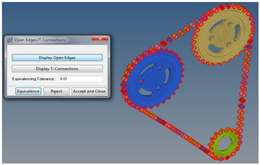
The equivalence operation merges such coincident nodes thereby stitching the elements together and closing the open edges.
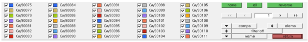
| Note | It is recommended to display components individually or display many components when they are sufficiently far apart over the Equivalencing Tolerance before performing the equivalence. Use the “d” shortcut key to bring up the display components panel. |
Thicken Shells
This utility can be used on components that have a surface mesh (also referred as shells). Generally legacy models built for contact simulation contain such meshes.
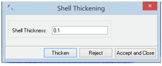
Shell Thickness
|
Provide a thickness value.
|
Thicken
|
Creates an offset surface mesh with the provided thickness value and adds side surfaces thereby creating a closed volume mesh.
|
Reject
|
Rejects the operation.
|
Accept and Close
|
Accepts the performed operation and closes the utility.
|
Fill Holes
Fill Holes can be used to cap uncapped holes.
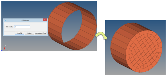
Hole Width
|
Provide a value for width of hole below which all displayed holes needs to be filled.
|
Hole Fill
|
Creates capped surface mesh for the open holes within the specified width thereby filling them.
|
Reject
|
Rejects the operation.
|
Accept and Close
|
Accepts the performed operation and closes the utility.
|
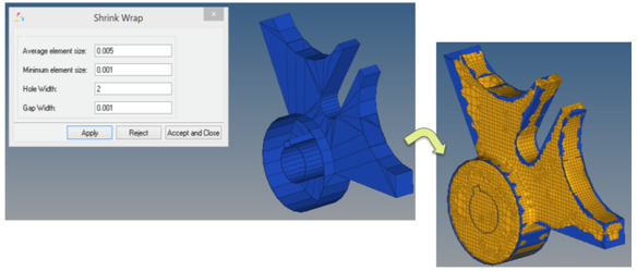
Shrink Wrap
The Shrink wrap tool creates a new component mesh by wrapping the exterior of the selected component. The wrap results in a closed surface wherever they are open.
This tool has following options:
Average element size
|
Average of the element size used to generate the mesh.
|
Minimum element size
|
Minimum size of element needed to create the mesh.
|
Hole width
|
Maximum width of the hole over which the wrap will be created.
|
Gap width
|
Maximum gap width over which the wrap will be created.
|
Apply
|
Creates the shrink wrap using the above parameters.
|
Reject
|
Rejects the operation.
|
Accept and Close
|
Accepts the performed operation and closes the utility.
|
Generally, the wrap does not result in a good quality mesh. A re-mesh (using the Re-Mesh tool) is recommended after generating the shrink wrap.
| Note | Upon clicking Apply, the new mesh is created in a different component collector overlaying on the existing one. The existing mesh gets replaced in the existing component upon clicking Accept and Close. |
Re-Mesh
The Re-mesh tool is a simple utility that can be used to replace an existing mesh on a component with a new one to obtain a more uniform good quality (aspect ratio appropriate for contact modeling) triangular mesh.
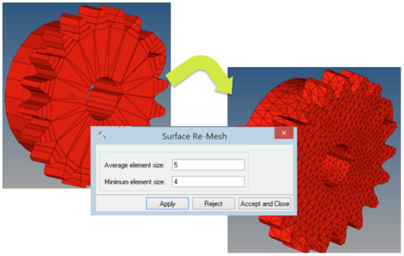
Average element size
|
Average of the element size used to generate the mesh.
|
Minimum element size
|
Minimum size of element needed to create the mesh.
|
Apply
|
Creates a new mesh from an existing one using the above parameters.
|
Reject
|
Rejects the operation.
|
Accept and Close
|
Accepts the performed operation and closes the utility.
|
| Note | Upon clicking Apply, the new mesh is created in a different component collector overlaying on the existing one. The existing mesh gets replaced in the existing component upon clicking Accept and Close. |
Working with legacy graphics
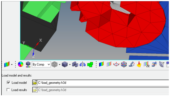
Prior to version 14.0, the contact algorithm in MotionSolve had a different criteria for mesh based contact simulation. As a result, it is possible that graphics in models having contacts might contain open surfaces, non-uniform mesh or just a surface(shell) mesh. To subject such graphics for mesh manipulation, the graphic h3d should be converted into a CAD or FE format so that the Import CAD or FE utility can use it as an input file. Follow the below steps to translate the graphic h3d to an FE format using HyperView.
| 1. | Load the graphic h3d with defective mesh in HyperView as the model input. Turn off the result input option as shown. Click Apply. |
| 2. | Go to File>Export>Solver Deck. |
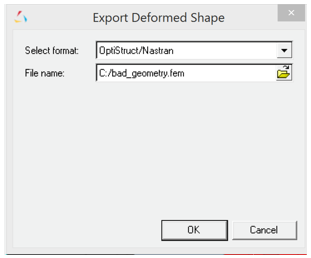
| 3. | In the Export Deformed Shape dialog, select Optistruct/Nastran from the Select format drop-down menu and provide a File name. Click OK. |
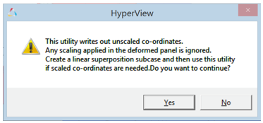
| 4. | A confirmation dialog appears warning the user that this utility exports only unscaled-coordinates. Click Yes. |
| 5. | In MotionView invoke the Import CAD or FE utility and select Optistruct as Input File format as shown below: |
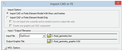
| 6. | Follow the rest of the process to access the Mesh Manipulation tool as described in the Mesh Manipulation Tool section above. |
See Also:
Contacts Panel
Contacts Post-Processing
Best Practices for Running 3D Contact Models in MotionSolve


