This section describes the Point to Curve (PTCV) Joint entity of MotionView and shows the various usage, creation, and editing methods.
Theory/Background
A Point to Curve Joint is a higher pair constraint. A fixed point on one body slides on a curve that is fixed on a second body. The point is not allowed to lift off the curve. The curve on the second body can be 2-D or 3-D and needs to be specified using a MotionView Curve (which is a reference entity).
Common Applications of PTCV Joints are:
| • | Non-Planar 3D Track Simulations |
The topological information required to define an PTCV Joint is shown in the figure below:
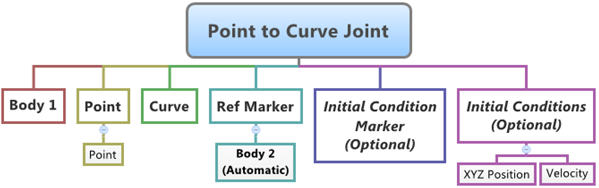
Entity Data Members
The data members of the PTCV Joint can be classified into the following members:
Connectivity
An PTCV Joint needs the following:
| • | Two Bodies – Body 1 and Body 2 |
| • | Location of Body 2 on the curve belonging to Body 2 – Point |
| • | Curve that belongs to Body 2 - Curve |
| • | Reference Marker on Body 2 which defines the coordinate system for the Curve, this marker also defines Body 2 of the joint – Ref Marker |
This advanced joint can only be modeled as a Single entity (it cannot be modeled as a Pair entity).
Properties
The PTCV Joint can have two types of Initial Conditions – Position and Velocity.
| • | The Position Initial condition for a PTCV Joint means that the starting point location of Body 1 that lies on the Curve of Body 2 – XYZ Position. |
| • | An Initial Velocity can be applied to the contact point on the curve as seen by an observer on the body containing the curve – Velocity. |
| • | Additionally, a Marker can be specified as a Reference marker for specifying the Position and Velocity initial conditions. By default this marker is set to the Joint Reference Marker that belongs to Body 2 – Initial Condition Marker. |
Creating and Editing Joints
To learn how to add a Point to Curve Joint to a model, please see the Joints topic.
Important Note - In order to completely specify a Point to Curve Joint, the following entities must be created first:
| 1. | A 2D or a 3D reference curve entity created using the Curves panel. |
| 2. | A Marker that belongs to Body 2 of the joint and is located appropriately so that the Curves entity can be meaningfully described as belonging to the Coordinate System of the Reference Marker. |
| 1. | Once an PTCV Joint has been added to the model using any of the "entity" creation methods, the panel for the joint will automatically be displayed in the panel area. See the panel example below: |
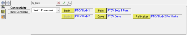
Joints Panel (PTCV Joint) – Connectivity Tab
| 2. | Although the joint definition needs two bodies to be specified (Body 1 and Body 2), only Body 1 can be specified manually. From Connectivity tab, select Body 1 by picking the body from the graphics area or double click the Body 1 collector to open to the model tree (from which the desired body can be selected). |
| 3. | Use the Point collector/model tree to specify the point of the PTCV joint (or pick the point from the graphics area). |
This will be the point that belongs to Body 1 and lies on the curve to be used for the joint.
| 4. | Use the Curve collector/model tree to select the curve that is to be used for the joint (or pick the curve from the graphics area). |
| 5. | Select the Curve Reference Marker (Ref Marker) that belongs to Body 2. |
The Body 2 field will now automatically display the body to which the Reference Marker belongs.
| 6. | Click on the Initial Conditions tab. |
| 7. | The default Initial Condition Marker for the joint is the Ref Marker that is specified on the Connectivity tab. To change this from the default, activate the User Initial Condition Marker check box and select the desired marker using the Marker collector. |
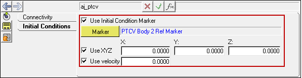
Joints Panel (PTCV Joint) – Initial Conditions Tab
| 8. | To specify an Initial Position for the Point to supersede those specified by the Point on the Connectivity tab, activate the Use XYZ check box and enter in the initial position values into the X, Y, and Z fields. |
| 9. | To specify an Initial Velocity for the joint, activate the Use velocity check box and enter the velocity value that is to be used in the field. |
|
| 1. | Left click the Advanced Joints panel icon  on the Constraint toolbar. on the Constraint toolbar. |
The Project Browser will filter the entities and display only the Advanced Joints in the model.
| 2. | Select the desired joint in the Project Browser. |
The corresponding panel is automatically displayed.
| 3. | From the Connectivity tab, use the Joint type drop-down menu to change the joint type, or use the collectors to change the bodies and other topological elements of the joint. |
|
Point to Curve Joint in MDL and XML Formats
The model containing the PTCV Joint can be saved in MDL format from MotionView and exported in the MotionSolve XML format.
Syntax:
*PointToCurveJoint(ptcv_name, "ptcv_label", body_1,
body_2,
point,
curve,
ref_marker,
[icm],
[ALLOW_COMPLIANCE],
Example:
*PointToCurveJoint(aj_ptcv, "Point to Curve Joint", b_ptcvb1, b_ptcvb2, p_ptcvb1, crv_ptcv, m_ptcvb2marker, aj_ptcv.rm)
To understand the complete syntax of the MDL statement, please refer to the *PointToCurveJoint() topic.
|
The *SetJointIC statement can be used for specifying initial conditions for the Point to Curve joint.
Syntax:
*SetJointIC(joint_name, ic_x_disp, ic_y_disp, ic_z_disp, ic_vel)
Example:
*SetJointIC(aj_ptcv, 20.14, 15.73, 0.0, 10)
To understand the complete syntax of this MDL statement, please refer to the *SetJointIC() topic.
|
To learn how to create a complete model using MDL Statements, please refer to tutorial MV-1070: Creating a Simple Pendulum System using MDL.
|
The PTCV Joint when exported to the MotionSolve XML format is defined as a Constraint_PTCV statement.
Syntax:
<Constraint_PTCV
id = "integer"
Lable = “Advance Joint Name”
i_marker_id = "integer"
j_marker_id = "integer"
[ disp_xo = "real"
disp_yo = "real"
disp_zo = "real"
vel_o = "real"
]
curve_id = "integer" >
/>
In case of the PTCV Joint the model statement will be as shown below:
<Constraint_PTCV
id = "301001"
label = "Point to Curve Joint"
i_marker_id = "30103020"
j_marker_id = "30102030"
disp_x0 = "20.143525"
disp_y0 = "15.737846"
disp_z0 = "0."
vel0 = "10."
curve_id = "301001"
/>
In the above XML Model statement the i_marker_id and j_marker_id represent the I and J markers of the Joint which belong to Body 1 and Body 2 respectively. To understand the complete syntax of the Constraint_PTCV XML model statement, please refer to the MotionSolve Reference Guide Page for Constraint_PTCV.
|
Creating and Editing Point to Curve Joints using Tcl
In MotionView, Tcl can be used to add any MDL entities to the model. There are two Tcl commands that can be used to add an entity:
Syntax:
mdlmodel_handle InterpretEntity new_handle keyword varname label
In case of the PTCV Joint the statement will look as shown below:
mdlmodel_handle InterpretEntity aj PointToCurveJoint aj_0 "\"Advanced Joint 0\"" b_0 b_1 p_0 crv_0 Global_Frame
|
The initial conditions for the Point to Curve Joint can be specified using the InterpretSet Tcl command.
Syntax:
mdlmodel_handle InterpretSet keyword tokens
In case of the PTCV Joint the statement will look as shown in the example below:
mdlmodel_handle InterpretSet SetJointICFlag aj_0 "true" "true"
mdlmodel_handle InterpretSet SetJointIC aj_0 20.14 15.73 0.0 10
|
The InterpretEntity command is used to add entities to the model and the InterpretSet command is used to set the entity properties. So in the case of the Point to Curve Joint, the properties that can be set are the Joint Initial Conditions. Extended definitions for InterpretEntity and InterpretSet can be found in the HyperWorks Desktop Reference Guide.
Note - When using the InterpretEntity and InterpretSet commands, it is important to also use the Evaluate command in order for the changes to take effect immediately.
To learn how to create a complete model using Tcl commands, please refer to tutorial MV-1040: Model Building Using Tcl.
See Also:
Advanced Joints Panel
Adding and Removing Entities
*PointToCurveJoint() (MDL Model Statement)
Constraint_PTCV (XML Command)
InterpretEntity (Tcl Command)
InterpretSet (Tcl Command)


