Connections Menu |

|

|

|

|
|
Connections Menu |
|
|
|

|
Connections Menu |
|
|
|
|
|
Connections Menu |
|
|
|
|
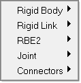
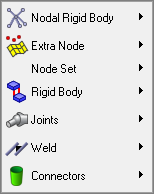
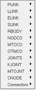
The Connections menu focuses on various connecting options to connect components of the crash model to complete the assembly. It also includes HyperMesh’s solver neutral connection definition through connectors. The menu varies, depending on the solver that is loaded.
|
|
|
|
RADIOSS |
|
LS-DYNA |
PAM-CRASH |
The following tools are available:
Nodal Rigid Body |
Create, edit and review nodal rigid bodies through the Rigids panel with elem types set to RgdBody (LS-DYNA only). |
Extra Node |
Create, edit and review Constrained_Extra_Nodes through the Groups panel with card image and type set to Xtranode (LS-DYNA only). |
Node Set |
Create, edit and review constrained_node_set through the Rigids panel with elem types set to ConNode (LS-DYNA only). |
Create, edit and review Joints through the FE Joints panel. |
|
Open the Rigids panel with the elem types field set to RBE2. |
|
Display all rigid bodies in the model; display individual rigid bodies; create new and edit existing, simple and complex rigid body formulations; and view and update details of individual rigid bodies, through the card editor and the Rigid panel. |
|
Create, edit and review Constrained_Rigid_Body through the Groups panel with card image and type set to Xtranode. |
|
Open the Rigids panel with the elem types field set to RLINK. |
|
Welds |
Create, edit and review welds through the Rigids panel with elem types set to GenWeld. |
Connectors submenu |
|
Create area-based connectors such as adhesives. |
|
Use a "dummy" connector entity to add mass to a part or create areas of mass to represent parts not present in the CAD or FE data. |
|
Creation of spotwelds based on user defined pitch on the selected part with automatic flange recognition. |
|
Create bolt connectors. |
|
Compares the model’s current connectors with a master connection file (MCF) so that you can quickly locate discrepancies. |
|
View and modify connectors in the current model. |
|
Add (absorb) existing FE weld entities as realization to connectors. |
|
Import Weld Points |
Import a master weld file that has connector location and the components that it connects. |
Perform FE quality checks on connector entities. |
|
Realize |
Realize the defined connector to FE entities based on the solver. |
Create line-based connections. |
|
Opens the Connector Spot panel, where you can create connectors that represent point connectors such as spot welds. |
|
Remove existing welds. |
|