The steps for creating a new clearance definition for a contact pair varies based on the type of clearance you select.
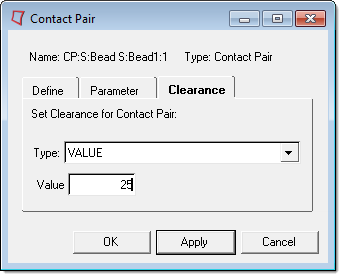
| 1. | In the Type field, select Value. |
| 2. | In the Value field, specify an initial clearance/overclosure for the entire set of slave nodes. |
| Note: | A positive values specifies an initial clearance, and a negative value specifies an initial overclosure. |
|
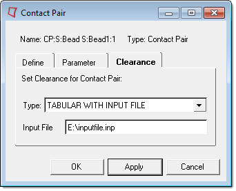
| 1. | In the Type field, select TABULAR WITH INPUT FILE. |
| 2. | In the Input File field, specify an input file that contains the clearance data.. |
| Note: | The input file can be a file name, relative path, or complete file path. A maximum of eighty characters are allowed in this field. |
|
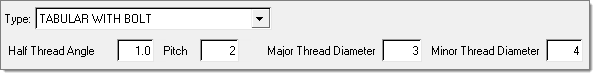
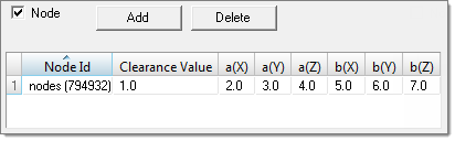
When using the TABULAR WITH BOLT clearance type, you can define clearance using nodes, node sets, or both nodes and node sets. In the example below, clearance is being defined using both nodes and node sets.
| 1. | In the Type field, select TABULAR WITH BOLT. |
| 3. | To define clearance with a node, select the node check box. |
| 4. | To add a data line to the table, click Add. |
| 5. | In the first data line, double-click the Node Id field. |
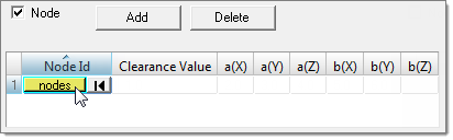
| 6. | Using the node collector, select a node. |
| 7. | To apply your selection and go back to the Contact Manager, click proceed. |
| 9. | To define clearance with a node set, select the Node set check box. |
| 10. | Optional: To create a new node set or edit an existing node set using the Entity Sets panel, click Create/Edit. |
| 11. | To add a data line to the table, click Add. |
| 12. | In the first data line, click the Node Set field and then select a node set from the list. |
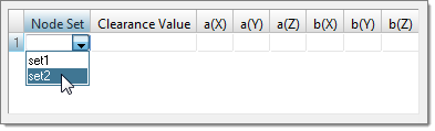
| 13. | Specify the following: |
|
When using the TABULAR WITH BOLT AND INPUT clearance type, you can define clearance using nodes, node sets, or both nodes and node sets. In the example below, clearance is being defined using both nodes and node sets.
| 1. | In the Type field, select TABULAR WITH BOLT AND INPUT. |
| 2. | To define clearance with a node, select the node check box. |
| 3. | To add a data line to the table, click Add. |
| 4. | In the first data line, double-click the Node Id field. |
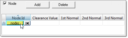
| 5. | Using the node collector, select a node. |
| 6. | To apply your selection and go back to the Contact Manager, click proceed. |
| 8. | To define clearance with a node set, select the Node set check box. |
| 9. | Optional: To create a new node set or edit an existing node set using the Entity Sets panel, click Create/Edit. |
| 10. | To add a data line to the table, click Add. |
| 11. | In the first data line, click the Node Set field and then select a node set from the list. |
| 12. | Specify the following: |
|
|


