Summary
Two overlapping plates (aluminum) are connected by a rivet (titanium) forming a lap joint. The aluminum and titanium materials are both defined by piece-wise linear elasto-plastic law. The plates and the rivet are meshed with solid elements. The free end of the bottom plate is constrained and the free end of the top plate is pulled (by applying imposed displacement) to shear the joint. An all inclusive contact is defined such that all the components in the model are master and all nodes of the model are slave.
This example is considered a static problem and the nonlinear implicit solver is used.
Title
Lap joint
|
|
Number
40.1
|
Brief Description
A lap joint is fixed at one end and pulled at the other to shear the joint.
|
Keywords
| • | Nonlinear large displacement analysis (NLGEOM) |
| • | Plasticity and Piece-wise linear elasto-plastic material (MATX36 and TABLES1) |
|
OptiStruct Options
| • | Parameters for Geometric Nonlinear Implicit Static Analysis Control (NLPARMX) |
| • | Boundary conditions (SPC) |
| • | Contact property for NLGEOM analysis (PCONTX) |
|
Input File
Lap_joint: <install_directory>/demos/hwsolvers/optistruct/lap_joint.fem
|
Technical / Theoretical Level
Beginner
|
Overview
Aim of the Problem
The purpose of this example is to demonstrate a nonlinear large displacement implicit analysis (NLGEOM) involving elasto-plastic material and contact using OptiStruct.
Physical Problem Description
The top and bottom plates have a length of 30mm, width of 20mm and height of 1.5mm. The rivet is 8mm in diameter and 6mm in height. The geometry of the joint is shown in Figure 1. Due to symmetry only half of the joint is modeled.
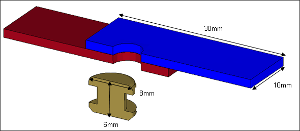
Fig 1: Geometry of the joint.
The material used for the aluminum plates have the following properties:
| • | Young’s modulus: 71700 MPa |
The stress vs plastic strain plot for aluminum is shown in Figure 2.
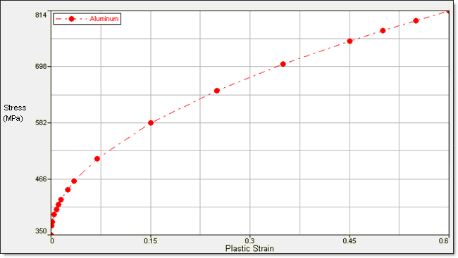
Fig 2: Stress – plastic strain curve for aluminum
The material used for the titanium rivet has the following properties:
| • | Young’s modulus: 112000 MPa |
The stress vs plastic strain plot for titanium is shown in Figure 3.
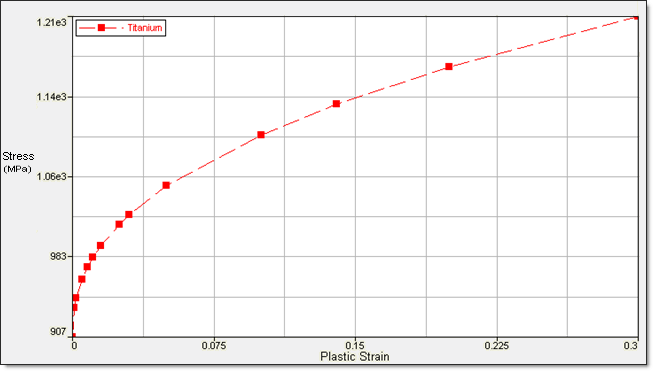
Fig 3: Stress – plastic strain curve for titanium
Analysis, Assumptions and Modeling Description
Geometric Linear (NLSTAT) or Geometric Nonlinear (NLGEOM) Analysis
In a geometric linear analysis all deformations and rotations are small – displacements of 5% of the model dimension are considered small.
For this lap joint example, the final deformations and strains after shearing of the lap joint are 9.5% of the largest dimension of the model (30mm). So, the geometrically nonlinear static NLSTAT analysis could not be considered for this example.
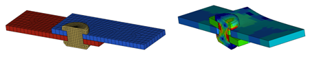
Modeling Methodology
The mesh is a regular solid mesh with the plates being around 1.5mm in dimension and the rivet being around 0.5mm in dimension.
The plates and rivet have been modeled using first order fully-integrated solid elements.
PSOLID 4 1
PSOLIDX 4 14 222 VAR
The boundary conditions applied in the model are shown in Figure 4.
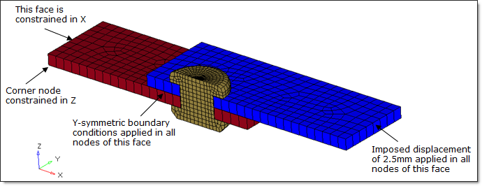
Fig 4: Boundary conditions
The imposed displacements are defined in FEM file using NLOAD1 card:
SPCD 3 572 1 2.5
………………
TABLED1 8 LINEAR LINEAR
+ 0.0 0.0 1.0 1.0ENDT
NLOAD1 7 3 DISP 8
OptiStruct Options Used
An all inclusive general purpose contact has been defined in the model. All the nodes of the model are defined as slave and all components in the model are defined as the master.
SET 2 GRID LIST
+ 1 2 3 4 5 6 7 8
+ 9 10 11 12 13 14 15 16
………………………………
SET 7 ELEM PROP
+ 4 5 6
CONTACT 6 7 2 7 OPENGAP
A small physical gap of around 0.02mm has been introduced between the top and bottom plates and also between the plates and the rivet. The minimum gap specified (0.022) for the contact is slightly higher than the physical gap for contact to take effect. A static Coulomb friction of 0.05 is defined for the interface.
PCONT 7 AUTO
PCONTX 7 0.05 0.022 0
+ CONST
+ 4
+
+ COUL STIFF
+
The plasticity and contact causes major nonlinearities; therefore, a static nonlinear analysis is performed using the arc-length displacement strategy. The time step is determined by a displacement norm control.
The nonlinear implicit parameters used are:
Implicit type:
|
Static nonlinear
|
Nonlinear solver:
|
BFGS Quasi-Newton method
|
Termination criteria:
|
Relative residual in force
|
Tolerance:
|
0.01
|
Update of stiffness matrix:
|
5 iterations maximum
|
Time step control method:
|
Arc-length
|
Initial time step:
|
0.01
|
Minimum time step:
|
1e-5
|
Maximum time step:
|
0.05
|
Line search method:
|
AUTO
|
Special Residual force computation with contact interfaces present:
|
0
|
Desired convergence iteration number:
|
6
|
Maximum convergence iteration number:
|
20
|
Decreasing time step factor:
|
0.8
|
Maximum increasing time step scale factor:
|
1.02
|
Arc-length:
|
Automatic computation
|
Spring-back option:
|
No.
|
A solver method is required to resolve Ax=b in each iteration of a nonlinear cycle. The linear implicit options used are:
Linear solver:
|
Direct (BCS)
|
Precondition methods:
|
Factored approximate Inverse
|
Maximum iterations number:
|
System dimension (NDOF)
|
Stop criteria:
|
Relative residual of preconditioned matrix
|
Tolerance for stop criteria:
|
Machine precision
|
The input nonlinear implicit options set in the FEM file are defined by NLPARMX:
NLPARM 9 100 P
+ 0.01
NLPARMX 9 0.0 0.1 0.01 -1 40
+ BFGS ARC 1e-5 0.05 AUTO
+
+ 6 1.02 20 0.8
Refer to the OptiStruct manual for more details about implicit options.
The nonlinear large deformation analysis has to be defined through a subcase. An NLPARM statement, as well as ANALYSIS=NLGEOM has to be present in the subcase. The termination time of 1.0s is defined through the TTERM entry.
SUBCASE 1
ANALYSIS NLGEOM
SPC = 10
NLPARM = 9
NLOAD = 7
TTERM = 1.000
Simulation Results and Conclusions
Animations
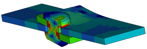
The displacement, stresses (mises) and plastic strain results after the shearing of the joint are shown in the following figures.
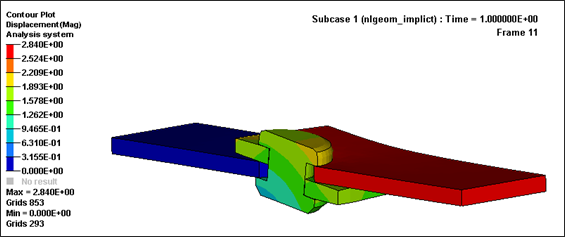
Fig 5: Displacements (max = 2.84mm)
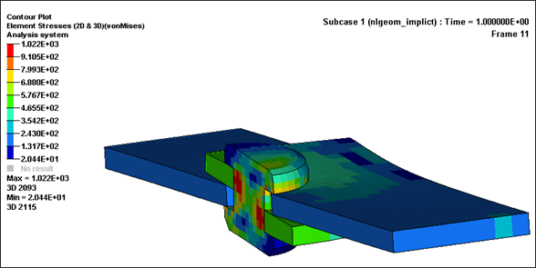
Fig 6: Stress (max = 1022 MPa)

Fig 7: Plastic strain in aluminum plates (max. = 23.86%).


