|
»Click here to display Table of Contents«
|

Materials/Failure |

|

|

|

|
|
Materials/Failure |
|
|

|

|
|
»Click here to display Table of Contents«
|
Materials/Failure |
|
|
|
|
|
Materials/Failure |
|
|
|
|
You can get data for Law 24 from the following tests:
With the following additional tests, material Law 24 will be more accurate (in fact, providing data fits the failure envelope):
‘ft’ is direct tensile strength. This test provides ‘ft/fc’ value for Law 24.
This test is also called Brazilian test. ‘Fst’ is splitting tensile strength in Splitting tensile test. Assuming that Fst=ft. Then you need to model this test to fit limit strength (ft) by validating ‘Ht’ value. This test should be with very slow velocity, so use HA8 solid property for in Splitting tensile test.
|
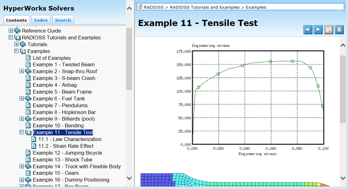
For elastic plastic laws in RADIOSS, one gives a true stress versus true strain curve, so you have to convert the experimental curve. How to proceed is described in the online documentation (Example 11: Tensile Test in the RADIOSS Tutorials and Examples manual):
For some other laws, other than the elastic plastic, such as Law 38 (Viscous elastic foam tabulated material), one gives directly an engineering stress versus engineering strain curve. |
WARNING ID: 519 ** WARNING IN SANDWICH SHELL INITIALIZATION SHELL (ID=…) MASS (TYPE NUMBER …) SUM OF LAYER MASS DIFFER FROM TOTAL WARNING ID: 520 ** WARNING IN SANDWICH SHELL INITIALIZATION SHELL (ID=…) INERTIA (TYPE NUMBER …) POTENTIAL INSTABILITY DUE TO LAYER INERTIA DISTRIBUTION
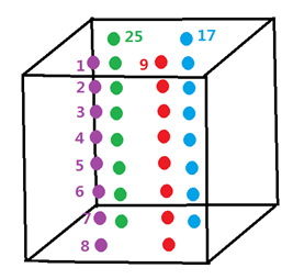
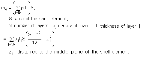
These messages concern a shell element using a property type 11 (“sandwich shell”). They mean that the mass (or inertia) of the shell, as it is computed from the characteristics of each layer (position, thickness, associated material), is not equal to the mass (or inertia) which is computed from the global material associated to the PART and the total thickness of the shell given in the property type 11. Indeed, mass me and inertia I of the element which will be distributed to the nodes of the shell are correctly computed from the characteristics of each layer:
The stability time step is computed from the global characteristics of the shell; it can not be ensured if the mass and inertia computed for the shell are not close enough to the mass and inertia which is computed from the density of the global material and the total thickness given in the shell property. So these messages are written if the relative error with respect to the mass (or inertia) computed from the global characteristics is greater than 1%. In order to ensure the stability, it is recommended to set a Young modulus for the global material, at least equal to the maximum modulus of the materials associated to all layers. |
The possible messages in case of failure criteria for shell elements using Law 25 are as follows: FAILURE-1: criteria FAILURE-2: criteria FAILURE-P: criteria Wpmax (maximum plastic work for failure) has been reached The concerned element identifier and the number of the layer that has failed are written. When the element is deleted (it depends on the failure of its different layers and on the flag Ioff - Total Element Failure Criteria - into the global material associated to the PART), the following message is written: RUPTURE OF SHELL ELEMENT … |
Depending on the material law, the solid elements are not deleted after the criteria For Material Laws 2, 4 and 22, only the deviatoric part of the stress tensor is set to zero, the internal pressure of the solid is still computed. On the other hand, for Material Laws 3, 23, 28 and 36 the solid elements are deleted when |
If number of integration points N=0 in /PROP/SHELL, then global integration approach is used. Global integration (N=0) is only compatible with Material Laws 1, 2, 22, 36, 43 and 60. Failure models are not available with global integration for shells. LAW1 is only available for global integration (N=0 or N>1 in /PROP/SHELL) and or membrane formulations (with NP=1 in /PROP/SHELL). Global integration option (N=0 in RADIOSS) directly computes the resultant stresses (F1, F2, F12, M1, M2, and M12) without considering the integration throughout thickness numerically (with classic strain, stress), so there is no value for SX_JJ, SY_JJ, SXY_JJ, SYZ_JJ, SZX_JJ with JJ=1,99 in /TH/SHELL. The default value for Iplas in case of Law 2 and global integration (N=0 in shell property) is Iplas =2: radial return. The default value for Iplas in case of Law 36 and global integration (N=0 in shell property) is Iplas =1: iterative projection. Using global integration approachFor elasto-plastic laws, this requires that yield criteria of plasticity be written with resultant stresses. Advantage of this option is, of course, the computation cost. Which is the cost like N=3. For drawback, it is the same behaviors which have been done throughout the thickness (especially for loading and unloading). For simple load cases, like monotone in loading and unloading, you can still get good results with less computation times by using the global integration approach. For complicated load cases, especially where loading and unloading happened differently throughout thickness, the precision of results might not be high enough by using the global integration approach. |