| 1. | Q4: original 4 nodes RADIOSS shell with hourglass perturbation stabilization. |
QEPH: formulation with hourglass physical stabilization for general use (istotropic + law25 shells only).
QBAT: modified BATOZ Q4 y24 shell with four Gauss integration points and reduced integration for in-plane shear. No hourglass control is needed for this shell.
DKT18: BATOZ DKT18 thin shell with three Hammer integration points.
| 2. | Small strain formulation is activated from time t =0, if Ismstr = 1 or 3. It may be used for a faster preliminary analysis, but the accuracy of results is not ensured. Any shell for which  can be switched to a small strain formulation by RADIOSS Engine option /DT/SHELL/CST, except if Ismstr = 4. can be switched to a small strain formulation by RADIOSS Engine option /DT/SHELL/CST, except if Ismstr = 4. |
| 3. | If Ithick or Iplas are activated, the small strain option is automatically deactivated in the corresponding type of element. |
| 4. | The hourglass formulation is visco-elastic for Q4 shells. |
| 5. | If the small strain option is set to 1 or 3, the strains and stresses which are given in material laws are engineering strains and stresses; otherwise they are true strains and stresses. |
| 6. | Iplas = 1 is available for Material Law 27. |
| 7. | Flag Istrain is automatically set to 1 for Material Law 25 and Law 27. |
| 8. | hm, hf, and hr are only used for Q4 shells. They must have a value between 0 and 0.05. |
| 9. | For hourglass type 3, hourglass maximum values may be larger, default values are 0.1 for hm and hr. |
| 10. | The default value of dm is 5% for Law 25 and Law 27. |
| 11. | The same default value of dm is used for QBAT shells, except for: |
| • | the default value of dm for QEPH is 1.5% for Material Laws 2, 19, 27, 32, 36 and 43 |
For further information about dm coefficient, refer to the RADIOSS Theory Manual.
| 12. | Shell numerical damping dn is only used for Ishell = 12 and 24: |
| • | for Ishell = 24, dn is used for hourglass stress calculation; |
| • | for QBAT, dn is used for all stress terms, except transverse shear; |
| • | for DKT18, dn is only used for membrane. |
| 13. | The default value of dn is: |
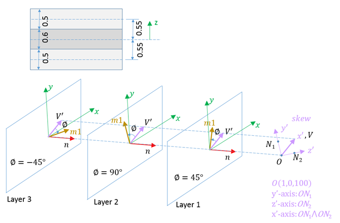
| 14. | Input components of global vector  used to define direction 1 of local coordinate system of orthotropy. Alternatively, it may be defined by a local skew system. used to define direction 1 of local coordinate system of orthotropy. Alternatively, it may be defined by a local skew system. |
| 15. | It is recommended to use Iplas = 1, if Ithick= 1. |
| 16. | Input components of the global vector  are defined in Line 6 with VX, VY and VZ. are defined in Line 6 with VX, VY and VZ. |
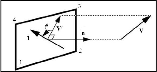
| 17. | Projection of vector  on shell element plane becomes vector on shell element plane becomes vector  |
| 18. | Direction 1 of local coordinate system of orthotropy is defined with vector  and angle and angle  (angle in degree). (angle in degree). |
| 19. | Input as many formats as number of layers (one format per layer, Line 7). |
| 20. |  is the angle between direction 1 of orthotropy and projection of vector is the angle between direction 1 of orthotropy and projection of vector  on the shell for layer i. on the shell for layer i. |
| 21. | Ipos = 0: layer positions are calculated automatically. If Thick is not equal to the sum of layer thicknesses, a warning message is displayed, and individual ply thickness will be adjusted such that the sum of the ply thicknesses will equal the total thickness which specified on Thick. |
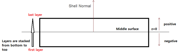
Multiple layers are allowed to have the same space position. In this case, Thick is not checked, as it does not need to be equal to the sum of layer thickness.
For more details, refer to Layer thickness and layer position calculation in FAQs.
| 22. | Each layer as well as the corresponding part must use the same material law, but may have different material properties, hence material IDs. RADIOSS checks for this condition and errors out if it is not met. Global material properties (membrane stiffness, bending stiffness, mass, and inertia) are calculated based on the material properties and layup (thicknesses, …). They are used for stability, mass and interface stiffness. A material is still required at part definition level, but is only used for pre- and post- (visualization “by material”) and its physical characteristics are ignored. The previous formulation where stiffness and mass were calculated from the material associated to the part is still used, if the version number of the input file is V13 or earlier. |
| 23. | Idrill is available for QEPH, QBAT (Ishell = 12 and 24), and standard triangle (C0) shell elements (Ish3n = 1 and 2). |
| 24. | Drilling DOF stiffness is recommended for implicit solutions especially for Riks method and bending dominated problems. |
|