|
»Click here to display Table of Contents«
|

Force: Field |

|

|

|

|
|
Force: Field |
|
|

|

|
|
»Click here to display Table of Contents«
|
Force: Field |
|
|
|
|
|
Force: Field |
|
|
|
|
Model Element |
|||||||||||||||||||||||||||||
Description |
|||||||||||||||||||||||||||||
Force_Field defines a force and torque acting between two Reference_Markers, I and J. The force and torque can only be a function of time and the relative displacement of the I and J Reference_Markers. The six components (three forces and three moments) are defined in the coordinate system of the J Reference_Marker. Both linear and non-linear relationships are supported. A linear Force_Field is defined directly in the XML input file. A nonlinear Force_Field is defined in a user-defined subroutine called FIESUB. |
|||||||||||||||||||||||||||||
Format |
|||||||||||||||||||||||||||||
<Force_Field id = "integer" [ label = "string" ] i_marker_id = "integer" j_marker_id = "integer" { usrsub_dll_name = valid_path_name usrsub_param_string = "USER( [[par_1 [, ...][,par_n]] )" usrsub_fnc_name = "custom_fnc_name" > | script_name = valid_path_name interpreter = "PYTHON" | "MATLAB" usrsub_param_string = "USER( [[par_1 [, ...][,par_n]] )" usrsub_fnc_name = "custom_fnc_name" > [[ length_x="real" length_y="real" length_z="real" length_tx="real" length_ty="real" length_tz="real" ]] [[ preload_x_X="real" preload_y="real" preload_z="real" preload_tx="real" preload_ty="real" preload_tz="real" ]] [[ K11="real" K12="real" K13="real" K14="real" K15="real" K16="real" K21="real" K22="real" K23="real" K24="real" K25="real" K26="real" K31="real" K32="real" K33="real" K34="real" K35="real" K36="real" K41="real" K42="real" K43="real" K44="real" K45="real" K46="real" K51="real" K52="real" K53="real" K54="real" K55="real" K56="real" K61="real" K62="real" K63="real" K64="real" K65="real" K66="real" ]] [[ CRATIO = "real" > | C11="real" C12="real" C13="real" C14="real" C15="real" C16="real" C21="real" C22="real" C23="real" C24="real" C25="real" C26="real" C31="real" C32="real" C33="real" C34="real" C35="real" C36="real" C41="real" C42="real" C43="real" C44="real" C45="real" C46="real" C51="real" C52="real" C53="real" C54="real" C55="real" C56="real" C61="real" C62="real" C63="real" C64="real" C65="real" C66="real" > ]] } </Force_Field> |
|||||||||||||||||||||||||||||
Attributes |
|||||||||||||||||||||||||||||
id |
Element identification number (integer>0). This number is unique among all Force_Field elements and uniquely identifies the element. |
||||||||||||||||||||||||||||
label |
The name of the Force_Field element. |
||||||||||||||||||||||||||||
i_marker_id |
Specifies the Reference_Marker at which the force is applied. This is designated as the point of application of the force. |
||||||||||||||||||||||||||||
j_marker_id |
Specifies the Reference_Marker at which the reaction force and moment are applied. This is designated as the point of reaction of the force. |
||||||||||||||||||||||||||||
usrsub_param_string |
The list of parameters that are passed from the data file to the user written subroutine, FIESUB. This attribute is common to all types of user subroutines and scripts. |
||||||||||||||||||||||||||||
usrsub_dll_name |
Specifies the path and name of the DLL or shared library containing user subroutine. MotionSolve uses this information to load the user subroutine in the DLL at run time. |
||||||||||||||||||||||||||||
usrsub_fnc_name |
Specifies an alternative name for the user subroutine FIESUB. |
||||||||||||||||||||||||||||
script_name |
Specifies the path and name of the user written script that contains the routine specified by usrsub_fnc_name. |
||||||||||||||||||||||||||||
interpreter |
Specifies the interpreted language that the user script is written in. Valid choices are MATLAB or PYTHON. |
||||||||||||||||||||||||||||
length_x length_y length_z length_tx length_ty length_tz |
These define the free length of the Force_Field element. In other words, the displacement from J to I, as measured by the J coordinate system when no external forces are acting on the element. Rotations are measured in terms of AX(I,J), AY(I,J), and AZ(I,J). They are assumed to be small angles (< 10 degrees). The data is optional. Their default values are 0. |
||||||||||||||||||||||||||||
preload_x preload_y preload_z preload_tx preload_ty preload_tz |
These define the pre-loads in the Force_Field element. In other words, the forces at I when there is no deformation. The force and torque components are measured in the J coordinate system. The data is optional. Their default values are 0. |
||||||||||||||||||||||||||||
K11 K12 K13 K14 K15 K16 K21 K22 K23 K24 K25 K26 K31 K32 K33 K34 K35 K36 K41 K42 K43 K44 K45 K46 K51 K52 K53 K54 K55 K61 K62 K63 K64 K65 K66 |
These define a 6x6 stiffness matrix that is used to calculate the spring force when a linear Force_Field is to be defined. The matrix need not be symmetric. It must, however, be positive semi-definite. In other words, xTKx >= 0 for any x. These entries are optional. They default to zero. It is convenient to define only those that are non-zero. |
||||||||||||||||||||||||||||
cratio |
Defines a damping scale factor. If this is specified, the damping matrix is calculated as C = cratio * K. A value of cratio = 0.01 is normally used. |
||||||||||||||||||||||||||||
C11 C12 C13 C14 C15 C16 C21 C22 C23 C24 C25 C26 C31 C32 C33 C34 C35 C36 C41 C42 C43 C44 C45 C46 C51 C52 C53 C54 C55 C56 C61 C62 C63 C64 C65 C66 |
These define a 6x6 damping matrix that is used to calculate the damping force for a linear Force_Field. The matrix need not be symmetric. However, it must be positive semi-definite. In other words, yTCy >= 0 for any y. These entries are optional. They default to zero. It is convenient to define only those entries that are non-zero. |
||||||||||||||||||||||||||||
Comments |
|||||||||||||||||||||||||||||
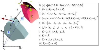
An exploded view of a Force_Field
|
|||||||||||||||||||||||||||||
Example |
|||||||||||||||||||||||||||||
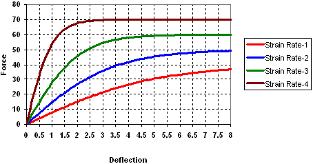
The first example demonstrates modeling of viscoelastic behavior in a bushing with a Force_Field. In nonlinear finite elements, it is common to model such effects using material laws and Maxwell elements. In MotionSolve, you can simply encapsulate this behavior in a FIESUB. The key aspect to viscoelastic behavior is that the force generated in the bushing is dependent on the strain-rate in the bushing. In MotionSolve, this is modeled as deflection-velocity (or deformation velocity) dependence. "Synthesized" test data for a viscoelastic bushing is shown in the figure below.
Sample test data for a viscoelastic bushing For this example, assume that a bushing was tested and that four force versus deflection curves (11-14) are available for different strain rates. These curves specify the dependency of the bushing force on the deflection for constant deflection-velocity along one of the translational directions. Similar curves are available for each of the other deflection components. Data for each component is provided in a separate matrix. The matrix IDs are passed to the FIESUB user defined subroutine through the parameter list. The bushing connects two Reference_Markers: "1801" on Body 18, and "1901" on Body 19. We want to model the nonlinear bushing damping force in MotionSolve. The Force_Field modeling element for this scenario is: <Force_Field id = "18" i_marker_id = "1801" j_marker_id = "1901" usrsub_dll_name = "C:\gates\Desktop\test\bush.dll" usrsub_param_string = "USER(11,12,13,14,15,16)" > </Force_Field> The user-subroutine, FIESUB, in the DLL "C:\gates\Desktop\test\bush.dll" is automatically loaded by MotionSolve. It is then invoked as needed to calculate the instantaneous force and/or the instantaneous stiffness and damping matrices. FIESUB Inputs - The following are provided as inputs:
FIESUB Outputs - The following are required as outputs:
The calling sequence for the FIESUB is shown below. Inputs are in blue and outputs are in red. CALL FIESUB (ID, TIME, PAR, NPAR, DISP, VELO, DFLAG, IFLAG, FIELD, DFDDIS, DFDVEL) Pseudo-code for a FIESUB that calculates the force and its partials for one viscoelastic bushing is shown below: FIESUB (...) { initialize force array to zero initialize stiffness matrix array to zero initialize damping matrix array to zero
if (initialization pass) { for each matrix k in the parameter list { define independent variable u = bushing deformation[k] define independent variable v = bushing deformation velocity[k] fit a surface through the data for matrix[k] store surface polynomial coefficients in global array[k] } return from FIESUB }
for each matrix k in the parameter list { set independent variable u = bushing deformation[k] set independent variable v = bushing deformation velocity[k] get data for surface polynomial from global array[k] set force [k] = interpolated value of surface polynomial k }
if (partial derivatives are needed) { for each matrix k in the parameter list { set independent variable u = bushing deformation[k] set independent variable v = bushing deformation velocity[k] get data for surface polynomial from global array[k] set stiffness [k,k] = partial of interpolated surface with u set damping [k,k] = partial of interpolated surface with v } } } |
|||||||||||||||||||||||||||||
Model Element |
|
Description |
|
FIELD defines a force and torque acting between two markers, I and J. The force and torque can only be a function of time and the relative displacement between the I and J markers. The six components (three forces and three moments) are defined in the coordinate system of the J marker. Both linear and non-linear relationships are supported. A nonlinear FIELD is defined in a user-defined subroutine called FIESUB. |
|
Declaration |
|
def FIELD(id, LABEL="", I=0, J=0, CRATIO=0.0, CMATRIX=[], KMATRIX=[], FORCE=[], LENGTH=[], FUNCTION="", ROUTINE="", INTERPRETER="", SCRIPT=""): |
|
Attributes |
|
id |
Element identification number (integer>0). This number is unique among all the FIELD elements and uniquely identifies the element. |
LABEL |
The name of the FIELD element. |
I |
Specifies the ID of the marker at which the force and moment is applied. This is designated as the point of application of the force. |
J |
Specifies the ID of the marker at which the reaction force and moment is applied. This is designated as the point of reaction of the force. |
CRATIO |
Defines a damping scale factor. If this is specified, the damping matrix is calculated as C = cratio * K. A value of cratio = 0.01 is normally used. |
CMATRIX |
These define a 6x6 damping matrix that is used to calculate the damping force for a linear FIELD. The matrix need not be symmetric. However, it must be positive semi-definite. In other words, yTCy >= 0 for any y. These entries are optional. They default to zero. It is convenient to define only those entries that are non-zero. |
KMATRIX |
These define a 6x6 stiffness matrix that is used to calculate the spring force when a linear FIELD is to be defined. The matrix need not be symmetric. It must, however, be positive semi-definite. In other words, xTKx >= 0 for any x. These entries are optional. They default to zero. It is convenient to define only those that are non-zero. |
FORCE |
These define the three translational preload force and three rotational preload torque in the FIELD element, measured in the J coordinate system. In other words, the forces at I when there is no deformation. The force and torque components are measured in the J coordinate system. The data is optional. Their default values are 0. |
LENGTH |
These define the free length of the FIELD element. In other words, the displacement from J to I, as measured by the J coordinate system when no external forces are acting on the element. Rotations are measured in terms of AX(I,J), AY(I,J), and AZ(I,J). They are assumed to be small angles (< 10 degrees). The data is optional. Their default values are 0. |
FUNCTION |
The list of parameters that are passed from the data file to the user written subroutine, FIESUB. This attribute is common to all types of user subroutines and scripts. |
ROUTINE |
Specifies an alternative name for the user subroutine FIESUB. |
INTERPRETER |
Specifies the interpreted language that the user script is written in. Valid choices are MATLAB or PYTHON. |
SCRIPT |
Specifies the path and name of the user written script that contains the routine. |
CommentsSee Force_Field |
|
ExampleThe example below shows how a FIELD may be defined. FIELD(18,LABEL="Field0",I=1801,J=1901,FUNCTION="USER(11,12,13,14,15,16)",ROUTINE="bush.dll::FIESUB") |
|
See Also:
The following MDL Model statements:
*SetField() - asymmetric field pair with user subroutine
*SetField() - single field with user subroutine
*SetField() - symmetric field pair with user subroutine
*SetFieldDamping() - asymmetric field pair
*SetFieldDamping() - single field
*SetFieldDamping() - symmetric field pair
*SetFieldForce() - asymmetric field pair
*SetFieldForce() - single field
*SetFieldForce() - symmetric field pair
*SetFieldLength() - asymmetric field pair
*SetFieldLength() - single field
*SetFieldLength() - symmetric field pair
*SetFieldStiffness() - asymmetric field pair