|
»Click here to display Table of Contents«
|

/INTER/TYPE20 |

|

|

|

|
|
/INTER/TYPE20 |
|
|

|

|
|
»Click here to display Table of Contents«
|
/INTER/TYPE20 |
|
|
|
|
|
/INTER/TYPE20 |
|
|
|
|
Block Format Keyword
/INTER/TYPE20 - Interface Type 20
Description
This is a general single surface or surface to surface contact interface. Edge to Edge contact is also possible. Penalty stiffness is constant and therefore the time step is not affected (for standard penalty stiffness). This contact interface can replace interface TYPE3, TYPE5, TYPE7, TYPE11 or TYPE19. The interface is basically defined in terms of one or two surfaces. If only one surface is used, this surface is self-impacting. If two surfaces are defined, nodes of surface two impact surface one. A symmetric treatment can be activated. Edges of surface one and two can be taken into account for the contact. Nodes can be added to surface.
(1) |
(2) |
(3) |
(4) |
(5) |
(6) |
(7) |
(8) |
(9) |
(10) |
/INTER/TYPE20/inter_ID/unit_ID |
|||||||||
inter_title |
|||||||||
surf_ID1 |
surf_ID1 |
Isym |
Iedge |
grnd_ID |
line_ID1 |
line_ID1 |
|
edge_angle |
|
|
|
|
|
Igap |
|
Ibag |
Idel |
|
|
|
|
|
|
Fpenmax |
|
|
|
|
|
Blank Format |
|||||||||
Required Fields
(1) |
(2) |
(3) |
(4) |
(5) |
(6) |
(7) |
(8) |
(9) |
(10) |
Stfac |
Fric |
Gap0 |
Tstart |
Tstop |
|||||
IBC |
|
|
Inacti |
VISS |
VISF |
|
|||
Ifric |
Ifiltr |
Xfreq |
Iform |
|
|
|
|
|
|
Read this input only if Ifric > 0 (Optional)
(1) |
(2) |
(3) |
(4) |
(5) |
(6) |
(7) |
(8) |
(9) |
(10) |
C1 |
C2 |
C3 |
C4 |
C5 |
|||||
Read this input only if Ifric > 1 (Optional)
(1) |
(2) |
(3) |
(4) |
(5) |
(6) |
(7) |
(8) |
(9) |
(10) |
C6 |
|
|
|
|
|
|
|
|
|
|
|
With,
With,
gm = 0 for brick elements
gs = 0 if the slave node is not connected to any element or is only connected to brick or spring elements.
If the slave node is connected to multiple shells and/or beams or trusses, the largest computed slave gap is used. If the free edge of a shell element is in contact, then Igap can shift the gap of the free edges border shells, as shown below:
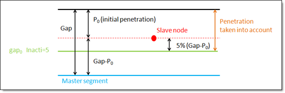
Inacti = 5: see figure below
If the initial penetration of a slave node is greater than the calculated maximum value (Fpenmax), the node will be deactivated from the interface (node stiffness deactivation).
Where, p is the pressure of the normal force on the master segment V is the tangential velocity of the slave node.
The following formulations are available:
Where,
If Ifiltr ≠ 0, the tangential forces are smoothed using a filter:
Where
The filtering coefficient Xfreq should have a value between 0 and 1.
While an adhesion force is computed as follows:
While an adhesion force is computed as follows:
Where, Vt is contact tangential velocity |

 , with
  , with
  for truss and beam elements, with
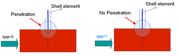
 if
if  if
if  if
if  , standard -3dB filter, with
  , and
, and