|
»Click here to display Table of Contents«
|

/INTER/TYPE21 |

|

|

|

|
|
/INTER/TYPE21 |
|
|

|

|
|
»Click here to display Table of Contents«
|
/INTER/TYPE21 |
|
|
|
|
|
/INTER/TYPE21 |
|
|
|
|
Block Format Keyword
/INTER/TYPE21 - Interface Type 21
Description
Specific interface between a non-deformable master surface and a slave surface designed for stamping. All nodes of the master surface must belong to the rigid body. Features of this interface:
| • | A node cannot be a slave and a master node at the same time. |
| • | The normals to the master segments must be oriented toward the slave surface. |
| • | For each slave node, a single impact will be retained, in a way which insures continuity of the normal force and the tangent force when this impact slides from one segment to a neighboring one. |
| • | Gap may vary according to the variation of shells and 3-node shells thickness, on the slave side. |
| • | Fast search algorithm. |
| • | High speed-up with SPMD version. |
(1) |
(2) |
(3) |
(4) |
(5) |
(6) |
(7) |
(8) |
(9) |
(10) |
/INTER/TYPE21/inter_ID/unit_ID |
|||||||||
inter_title |
|||||||||
surf_IDs |
surf_IDm |
Istf |
Ithe |
Igap |
|
|
|
|
Iadm |
Fscalegap |
Gapmax |
DEPTH |
Pmax |
|
|
||||
Stmin |
Stmax |
|
|
|
|
|
|
||
Stfac |
Fric |
Gapmin |
Tstart |
Tstop |
|||||
IBC |
|
|
Inacti |
VISS |
|
|
Bumult |
||
Ifric |
Ifiltr |
Xfreq |
|
sens_ID |
fct_IDF |
AscaleF |
|
||
(1) |
(2) |
(3) |
(4) |
(5) |
(6) |
(7) |
(8) |
(9) |
(10) |
C1 |
C2 |
C3 |
C4 |
C5 |
|||||
(1) |
(2) |
(3) |
(4) |
(5) |
(6) |
(7) |
(8) |
(9) |
(10) |
C6 |
|
|
|
|
|||||
(1) |
(2) |
(3) |
(4) |
(5) |
(6) |
(7) |
(8) |
(9) |
(10) |
NRadm |
Padm |
Angladm |
|
|
|
|
|
||
Kthe |
fct_IDK |
AscaleK |
Tint |
Ithe_form |
|
|
|||
Frad |
Drad |
Fheat |
|
|
|
|
|||
IDrby |
IDref |
Damp |
Dampr |
|
|
|
|||
|
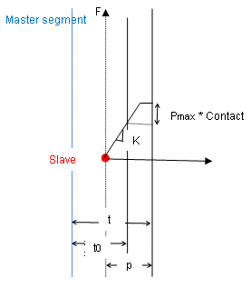
Gap is constant over the slave surface and along the time, equal to Gapmin. And a default value for Gapmin is computed as t/2, t being the average thickness of the slave shell elements. In case of constant gap, Gapmax and Fscalegap will not be used. If contact thickness of the part is not define in input /PART:
and will vary along the time according to the variation of shells and 3-node shells thickness, on the slave side. If contact thickness of the part is define in input /PART:
Where,
If Igap = 1 or 2, the variable gap is always at most equal to Gapmax and default value for Gapmax will be set to 1030 and is always at least equal to Gapmin (but there is no default value for Gapmin).
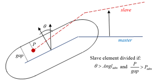
If the contact occurs in a zone (master side) whose radius of curvature is lower than the element size (slave side), the element on the slave side will be divided (if not yet at maximum level).
If the contact occurs in a zone (master side) whose radius of curvature is lower than NRadm times the element size (slave side), the element on the slave side will be divided (if not yet at maximum level). If the contact occurs in a zone (master side) where the angles between the normals are greater than Angladm, and the percentage of penetration is greater than Padm, the element on the slave side will be divided (if not yet at maximum level).
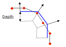
A default value for DEPTH is computed as the maximum of:
If the input value is not equal to 0, DEPTH will be raised up to the upper value of the gap (at time 0) among all nodes. Too large DEPTH will decrease the performances of search algorithms for contact.
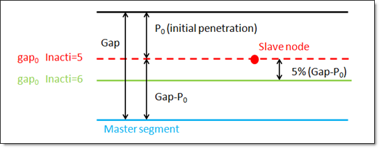
Inacti = 5 or Inacti = 6, the gap is initially reduced and recovers its computed value as the slave node depenetrates. Inacti = 6 is recommended instead of Inacti =5, to avoid high frequency effects into the interface.
Fric is Coulomb friction
Fric becomes a scale factor of Coulomb friction coefficient which depends on the temperature.
While,
Where, p is the pressure of the normal force on the master segment V is the tangential velocity of the slave node.
The following formulations are available:
Where,
While and adhesion force is computed as follows:
Where, Vt is the tangential relative velocity of the slave node with the master segment If Ifiltr ≠ 0 , the tangential forces are smoothed using a filter:
Where
The filtering coefficient Xfreq should have a value between 0 and 1. By Ithe= 1 (heat transfer activated) to consider heat exchange and heat friction in contact.
Tint is used only when Ithe_form= 0. In this case. The temperature of master side assumed to be constant (equal to Tint). If Ithe_form= 1 then Tint is not take into account. So the nodal temperature of master side will be considered If Ithe = 2, Heat transfer is computed using thermal conductance Kthe only for the slave side. The temperature of the master side is not assumed to be a constant but is calculated from the temperature field defined on each master node. These nodal temperatures can vary over time and space which are defined using /IMPTEMP.
Thermal conduction Ithe = 1 needs the material of the slave side to be a thermal material using finite element formulation for heat transfer (/HEAT/MAP). Thermal conduction is computed when the slave node falls into gap:
Heat exchange coefficient
While fK is function of fct_IDK
Radiation is considered in contact if
While Drad is the Maximum distance for radiation computation. The default value for Drad is computed as the maximum of:
It is recommended not to set the value too high for Drad, which may reduce the performance of RADIOSS Engine. A radiant heat transfer conductance is computed as:
with
Where,
A damping force (resp. torque) is applied to the tool:
With Where, C is a percentage of the critical damping with the tool mass Mass (resp. inertia I) K is the total interface stiffness (resp. rotational stiffness Kr).
|


 , with
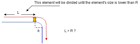
 , standard -3dB filter, with
  , and
, and 
 is the Stefan Boltzman constant,