|
»Click here to display Table of Contents«
|

PBEAM |

|

|

|

|
|
PBEAM |
|
|

|

|
|
»Click here to display Table of Contents«
|
PBEAM |
|
|
|
|
|
PBEAM |
|
|
|
|
Bulk Data Entry
PBEAM – Beam Property
Description
The PBEAM bulk data entry defines the properties of beam elements defined via the CBEAM entry.
Format
(1) |
(2) |
(3) |
(4) |
(5) |
(6) |
(7) |
(8) |
(9) |
(10) |
PBEAM |
PID |
MID |
A(A) |
I1(A) |
I2(A) |
I12(A) |
J(A) |
NSM(A) |
|
|
C1(A) |
C2(A) |
D1(A) |
D2(A) |
E1(A) |
E2(A) |
F1(A) |
F2(A) |
|
The following two continuation lines may be repeated up to ten times. They are used to define stations along the beam element.
|
SO |
X/XB |
A |
I1 |
I2 |
I12 |
J |
NSM |
|
|
C1 |
C2 |
D1 |
D2 |
E1 |
E2 |
F1 |
F2 |
|
The last two continuation lines are:
|
K1 |
K2 |
|
|
NSIA |
NSIB |
|
|
|
|
M1A |
M2A |
M1B |
M2B |
N1A |
N2A |
N1B |
N2B |
|
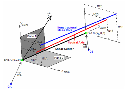
Fig 1: Beam Element Coordinate System (for PBEAM entry)
This example represents a straight beam with stress recovery, only at end A.
|
This example represents a tapered beam with an intermediate section defined halfway along its length and stress recovery at both end A and end B. Note that the blank line after YES is entered for Stress Output (SO) at end B.
|
Field |
Contents |
PID |
Property identification number. No default (Integer > 0) |
MID |
Material identification number. See comment 1. No default (Integer > 0) |
A(A) |
Area of beam cross-section at end A. No default (Real > 0.0) |
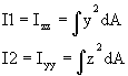
I1(A) |
Area moment inertia in plane 1 about the neutral axis at end A. No default (Real > 0.0) |
I2(A) |
Area moment inertia in plane 2 about the neutral axis at end A. No default (Real > 0.0) |
I12(A) |
Area product inertia at end A ( Default = 0.0 (Real) |
J(A) |
Torsional stiffness parameter at end A. Default = 0.0 (Real > 0.0) |
NSM(A) |
Nonstructural mass per unit length at end A. Default = 0.0 (Real) |
Ci(A), Di(A), Ei(A), Fi(A) |
The y and z locations in element coordinates for stress data recovery at end A. (i=1 is y and i=2 is z) Default = 0.0 for all entries (Real) |
SO |
Stress output request option for intermediate stations and end B. See comments 5 through 8. If set to NO, the following continuation line (containing fields C1 through F2) must be omitted for that intermediate station, and no stresses are recovered for that intermediate station. If set to YESA, the following continuation line (containing fields C1 through F2) must be omitted for that intermediate station, and stresses, for that intermediate station, are recovered at the stress recovery locations identified for end A. If set to YES, the following continuation line (containing fields C1 through F2) must contain the same stress recovery locations as the first continuation line (containing fields C1(A) through F2(A)) or must be entirely blank. Default = YES (YES, YESA, or NO) |
X/XB |
Fractional distance of the intermediate station from end A. Default = 1.0 (Real > 0.0) |
A |
Area of beam cross-section for intermediate stations. Default = A(A) (Real > 0.0) |
I1 |
Area moment inertia in plane 1 about the neutral axis for intermediate stations. Default = I1(A) (Real > 0.0) |
I2 |
Area moment inertia in plane 2 about the neutral axis for intermediate stations. Default = I2(A) (Real > 0.0) |
I12 |
Area product inertia for intermediate stations ( Default = I12(A) (Real) |
J |
Torsional stiffness parameter for intermediate stations. Default = J(A) (Real > 0.0) |
NSM |
Nonstructural mass per unit length for intermediate stations. Default = NSM(A) (Real) |
Ci, Di, Ei, Fi |
The y and z locations in element coordinates for stress data recovery for intermediate stations. (i=1 is y and i=2 is z). See comments 5 through 8. Default = 0.0 for all entries. (Real) |
K1,K2 |
Shear stiffness factor K in K*A*G for plane 1 and plane 2. Default = 1.0 for both (Real) |
NSIA |
Nonstructural mass moment of inertia per unit length about nonstructural mass center of gravity at end A. Default = 0.0 (Real) |
NSIB |
Nonstructural mass moment of inertia per unit length about nonstructural mass center of gravity at end B. Default = NSIA (Real) |
M1A, M2A |
(y,z) coordinates of center of gravity of nonstructural mass at end A. Default = 0.0, 0.0 (Real) |
M1B, M2B |
(y,z) coordinates of center of gravity of nonstructural mass at end B. Default = M1A, M2A (Real) |
N1A, N2A |
(y,z) coordinates of neutral axis at end A. Default = 0.0, 0.0 (Real) |
N1B, N2B |
(y,z) coordinates of neutral axis at end B. Default = N1A, N2A (Real) |
| 1. | For structural problems, MID may reference only a MAT1 material entry. For heat transfer problems, MID may reference only a MAT4 material entry. |
| 2. | Blank fields for K1 and K2 are defaulted to 1.0. If a value of 0.0 is used for K1 and K2, the transverse shear flexibilities are set to 0.0. |
| 3. | One value for X/XB must be 1.0. |
| 4. | The moments of inertia are defined as follows: |
| 5. | Stress recovery is only allowed at end A and end B. Stress recovery at intermediate stations is not supported. |
| 6. | If no stress data at end A is to be recovered, but a stress recovery location is defined for end B, then the first continuation entry, which contains the fields C1(A) through F2(A), may be omitted. |
| 7. | If the continuation line containing values C1 through F2 is entirely blank for end B, the stress recovery locations defined for end A are used. However, if any entry is defined on this line, then all blank entries will default to 0.0 and not the corresponding entry for end A. |
| 8. | Stress recovery locations must be the same for end A and end B. |
| 9. | OSDIAG, 166, 1 may be input in the I/O options section of the input deck to bypass error terminations caused by PBEAM definitions which violate the rules outlined in comments 5 and 8. In such instances, the following occurs: |
| • | Warning messages regarding the violations are echoed to the .out file. |
| • | Stress is not recovered at intermediate stations. |
| • | Recovery locations defined for end A are also used for end B. |
| 10. | For tapered beams, a single prismatic beam is created with properties obtained by weighted averaging of all station properties. |
| 11. | The cross-sectional properties have to be specified fully for end A. For end B, blank fields mean that the properties are the same as for end A. For intermediate stations, blank fields result in a linear interpolation between the property value at end A and end B being used. |
| 12. | The NSM specified at end A is the default value for NSM at end B. The default for all other stations is a linear interpolation between end A and end B. So, for a constant NSM over the length of the beam, only NSM at end A is required. |
The mass of the element is calculated as:
| Mass = density * beam_area * beam_length + NSM * beam_length |
If the NSM value is different in different stations, it is averaged over all the stations and the average is used in the element calculation.
| 13. | This card is represented as a property in HyperMesh. |
See Also: