|
»Click here to display Table of Contents«
|

PGAP |

|

|

|

|
|
PGAP |
|
|

|

|
|
»Click here to display Table of Contents«
|
PGAP |
|
|
|
|
|
PGAP |
|
|
|
|
Bulk Data Entry
PGAP – Gap Element Property
Description
Defines properties of the gap (CGAP or CGAPG) elements.
Format
(1) |
(2) |
(3) |
(4) |
(5) |
(6) |
(7) |
(8) |
(9) |
(10) |
PGAP |
PID |
U0 |
F0 |
KA |
KB |
KT |
MU1 |
MU2 |
|
|
|
|
|
GPAD |
FRICESL |
|
|
|
|
Frictionless contact with automatic determination of U0 and KA:
Minimum data required for Coulomb friction:
Enforced stick condition (See comment 8):
|
Field |
Contents |
||||
PID |
Property identification number. No default (Integer > 0) |
||||
U0 |
Initial gap opening. Default = 0.0 (Real or AUTO). See comment 2. |
||||
F0 |
Preload. (Ignored in linear analysis). Default = 0.0 (Real > 0.0) |
||||
KA |
Axial stiffness for the closed gap. See comments 3 and 7. Positive value (KA = Real > 0.0) is directly prescribed stiffness. Negative value (KA = Real < 0.0) defines a stiffness scaling factor. The stiffness scaling factor is equal to |Real < 0.0|. The scaling is applied to the automatic stiffness value (the stiffness value when KA = AUTO). No default (AUTO, SOFT, HARD, Real > 0.0, or Real < 0.0) |
||||
KB |
Axial stiffness for the open gap. See comment 3. Default = 10-14 * KA (Real > 0.0). This default is also set when KB=0. |
||||
KT |
Transverse stiffness when the gap is closed. See comments 4 and 7. Default = MU1 * KA (Real > 0.0 or AUTO) |
||||
MU1 |
Coefficient of static friction (ms). See comments 4, 8 through 10. Default = 0.0 (Real > 0.0, STICK or FREEZE) |
||||
MU2 |
Coefficient of kinetic friction (mk). See comments 4, 8 through 10. Default = MU1 (0.0 < Real < MU1) |
||||
GPAD |
“Padding” to be added to account for additional layers on the surface of obstacles A and B. Positive value reduces the initial gap opening. See comment 11. Default = NONE (Real, NONE, or THICK; THICK applies only to CGAPG elements) |
||||
FRICESL |
Frictional elastic slip – distance of sliding up to which the frictional transverse force increases linearly with slip distance. Specified in physical distance units (similar to U0 and GPAD). See comment 5.
Default = 0.0 (Real > 0.0) |
Comments
| 1. | The gap element coordinate system is presented in the following figure. See the CGAP or CGAPG entry for a more detailed description. |
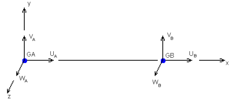
The CGAP or CGAPG Element Coordinate System
| 2. | With the optional value AUTO, the initial gap opening U0 is calculated automatically, based on the distance between nodes GA and GB (in the original, undeformed mesh). For gap elements with set coordinate systems, this becomes a projection of vector GA->GB onto the prescribed axis on the gap element (axis 1 of the coordinate system). |
| 3. | The gap element force-displacement behavior is different in linear and nonlinear analysis (see Small Displacement Nonlinear Analysis for more information on nonlinear solutions). In linear analysis, the gap stiffness is constant and depends on the initial gap opening U0 (as shown in the figure below). |
CGAP or CGAPG Element Force Deflection Curve for Linear Analysis
The gap force displacement behavior in nonlinear analysis is illustrated in the figure below. While the gap is open, its normal stiffness is defined by KB. When the gap relative displacement, UA - UB becomes equal to the initial opening U0, first contact occurs. The gap stiffness becomes KA upon contact.
CGAP or CGAPG Element Force Deflection Curve for Nonlinear Analysis
| 4. | When the gap is open, there is no transverse stiffness. When the gap is closed, friction is activated and the gap has stiffness KT in the transverse direction (see 5 below for alternative version). KT acts as a linear spring in linear solution sequences. For nonlinear solution sequences, frictional force increases with sliding distance in proportion to KT until it reaches static friction force MU1 * Fx, Fx being the normal force in the gap element. With further transverse deformation, friction becomes kinetic and the friction force is MU2 * Fx. See the figure below for a one-dimensional illustration. |
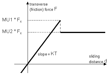
CGAP or CGAPG Element Frictional Behavior in Nonlinear Analysis
| 5. | In addition to the above formulation, in Release 12.0 an additional model of friction has been introduced, based on Elastic Slip Distance and activated by presence of non-zero FRICESL. This model typically has better performance in solution of frictional problems due to more stable handling of transitions from stick to slip. Key differences between the two available models are illustrated in the figure below (F1 and F2 represent two different values of normal force Fx): |
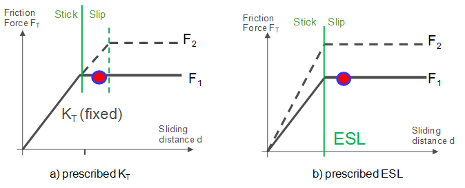
Comparison of the two friction models for gap elements.
| • | Model (a), based on fixed stiffness KT, is relatively simpler and only requires a coefficient of friction MU1 and MU2 (while KT can be determined automatically). However, in Coulomb friction the frictional resistance depends upon normal force. Using fixed KT will predict different range of stick/slip boundary for different normal forces, and thus may qualify the same configuration as stick or slip, depending on normal force. |
| • | Model (b), based on Elastic Slip Distance, provides unique identification of stick or slip and generally performs better problem solving with friction. This model does require setting elastic slip distance FRICESL (for gap elements, there is no automatic determination of FRICESL – a recommended value is about 0.5% of typical element size in the neighborhood of the gap element). |
| 6. | Note that the nonlinear gap element's force-displacement behavior may produce negative contributions to the compliance of the structure. For example, if KB > 0 and initial gap opening U0 > 0, then the gap is essentially "preloaded" with an attractive force KB*U0. As such a gap closes, the work done (and, hence, the gap's contribution to compliance) is negative. Such very small negative contributions may even be produced if the KB field is blank or zero – this is due to the default non-zero value of KB applied in such cases. In most situations, such small negative contributions get overridden by the overall positive compliance of the entire structure. However, in some cases they may lead to negative total compliance. |
| 7. | Reasonable gap stiffness: the gap stiffness values KA and KT essentially represent penalty springs that are hard enough to prevent perceptible penetration of contacting nodes. While, theoretically, higher stiffness values enforce the contact conditions more precisely, excessively high values may cause difficulties in convergence or poor conditioning of the stiffness matrix (this is especially true for KT). If any such conditions are observed, it may be beneficial to reduce the value of gap stiffness. A reasonable range of gap stiffness is of the order of: |
(103 to 106 ) * E * h
Where, E is the typical value of elastic modulus and h is the typical element size in the area surrounding the gap elements. Such a range will generally keep the gap penetration below one thousandth / one millionth of the element size, respectively. A good value for KT is of the order of 0.1*KA.
To facilitate reasonable values of KA and KT, automatic calculation of these parameters is supported, specifically:
| • | Option KA=AUTO determines the value of KA for each gap element using the stiffness of surrounding elements. Additional options SOFT and HARD create respectively softer or harder penalties. SOFT can be used in cases of convergence difficulties and HARD can be used if undesirable penetration is detected in the solution. |
| • | Option KT=AUTO automatically calculates the value of KT. If MU1>0, the result here is the same as with blank KT - its value is calculated as MU1*KA. However, if MU1=0 or blank, KT=AUTO produces a non-zero value of KT, calculated as KT=0.1*KA. Therefore, KT=AUTO can be used to prescribe enforced stick conditions (see below). |
| • | A negative value for KA indicates that a stiffness scaling factor equal to |Real < 0.0| is defined. This scaling is applied on the stiffness value via KA = AUTO. |
| 8. | MU1=STICK is interpreted as an enforced stick condition. (This can also be accomplished by setting KT>0 or KT=AUTO with MU1=0 or blank). Such gap elements will not enter the sliding phase. Of course, the enforced stick only applies to gaps that are closed. Note that, in order to effectively enforce stick condition on gaps of non-zero length, frictional offset may need to be turned off (See comment 10). |
| 9. | MU1=FREEZE enforces zero relative motion of the gap – the gap opening remains fixed at the original value and the sliding distance is zero. Also, rotations at GA node are matched to the rotations of GB or the obstacle patch B. The FREEZE condition applies no matter whether the gap is open or closed (hence, U0 is of no relevance in this case). The values of KB and KT are ignored. The value of KA is respected, although it is recommended that it is set to AUTO or HARD, to assure good connection. Also, this condition is effective irrespective of the frictional offset setting. |
| 10. | The presence of friction or stick can introduce moment loadings and counter-intuitive results into the problem by way of frictional offset. The reason is that for gap elements with non-zero length (distance between GA and GB), the actual location of the contact interface is presumed to be in the middle of the gap length (see figure below). |
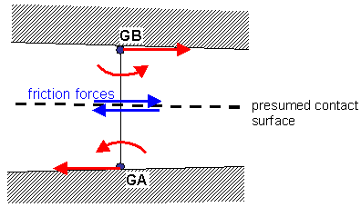
CGAP or CGAPG Presumed Contact Surface
The frictional forces act along this contact surface. Transferring these forces to the grid points GA and GB requires an offset operation that produces both forces and moments at the gap grid points. Similarly, the sliding distance at the gap interface is a result of nodal displacements and rotations at GA and GB (see figure below).
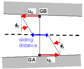
CGAP or CGAPG Sliding with Friction
For contact between bodies that do not support moments (solid elements, for example), this offset may render friction ineffective because the free rotations at gap nodes offer no effective resistance to friction. With the stick condition formally satisfied, for example, nodes GA and GB can move relative to each other (see figure below).
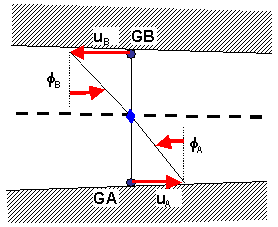
CGAP or CGAPG Stick (Zero Sliding Distance)
In practice, for gaps that are initially open, AUTOSPC will effectively fix respective unsupported rotations. However, for gap elements that are initially closed (U0 < 0 or U0=AUTO with CID=FLIP), the frictional terms will prevent AUTOSPC from being effective. Hence, respective SPC on rotations need to be applied manually. (Note that this only applies to "individual" gap end nodes GA and GB and is not needed for elements or patches of nodes on the obstacle side of GAPG elements).
Effective in the Release 12.0, to avoid such counter-intuitive behavior, the frictional offset operation is by default turned off if the model involves friction or stick and contains at least one nonlinear subcase (of NLSTAT type). (Note that for consistency, this affects both linear and nonlinear gap elements.) This produces more intuitive results with friction. However, it may violate the rigid body balance of the body.
For linear gap analysis and for FREEZE condition, the offset operation is applied by default (this produces correct rigid body balance, especially in natural frequency analysis).
The above default setting can be changed via the GAPOFFS command on the GAPPRM card.
| 11. | The GPAD option allows you to account for additional layers on the surface on obstacles A and B, such as shell thickness or coatings on the surface of solids. A positive value substracts from the gap opening U0, when calculated using AUTO option (GPAD is only allowed when U0 is set to AUTO). |
The GPAD option THICK automatically accounts for shell thickness on both sides of the gap (this also includes the effects of shell element offset ZOFFS or composite offset Z0). The THICK option applies only to CGAPG elements and is ignored for CGAP.
| 12. | Applying rotational SPC on nodes which belong to a FREEZE contact should be avoided. Fixing the rotational degrees of freedom will prevent the rotation of these contact nodes even in the case of solid elements. |
| 13. | This card is represented as a property in HyperMesh. |
See Also: