|
»Click here to display Table of Contents«
|

CGAP |

|

|

|

|
|
CGAP |
|
|

|

|
|
»Click here to display Table of Contents«
|
CGAP |
|
|
|
|
|
CGAP |
|
|
|
|
Bulk Data Entry
CGAP – Gap Element Connection
Description
Defines a gap or friction element.
Format
(1) |
(2) |
(3) |
(4) |
(5) |
(6) |
(7) |
(8) |
(9) |
(10) |
CGAP |
EID |
PID |
GA |
GB |
GO/X1 |
X2 |
X3 |
CID |
|
Minimum necessary data when GA and GB are not coincident:
|
Field |
Contents |
EID |
Unique element identification number. No default (Integer > 0) |
PID |
PGAP entry identification number. Default = EID (Integer > 0) |
GA,GB |
Connected grid points at ends A and B. No default (Integer > 0; GA ≠ GB) |
X1, X2, X3 |
Components of the orientation vector, from GA, in the displacement coordinate system at GA. Default determined automatically (Comment 7). (Real) |
G0 |
Alternate method to supply orientation vector, using grid point G0. Direction of orientation vector is from GA to G0. No default (Integer > 0) |
CID |
Element coordinate system identification number. CID must be specified if GA and GB are coincident (distance from GA to GB < 10-4). Alternatively: FLIP – reverses the direction of the gap axis (Comment 5). Default = blank (Integer > 0 or flip or blank) - See comments 2 through 6. |
| 1. | For linear subcases, the CGAP element will produce a linear stiffness matrix which remains linear with the initial stiffness. The stiffness used depends on the value for the initial gap opening (U0 field in the PGAP entry). |
| 2. | The gap element coordinate system is defined by one of the following methods: |
| • | CID: If the coordinate system CID is specified, the element coordinate system is established using that coordinate system. In this case, the element x-axis is in the coordinate system’s 1-direction, and the y-axis is in the coordinate system’s 2-direction (for rectangular coordinate systems; the 1-direction is the x-direction and the 2-direction is the y-direction). The orientation vector will be ignored in this case. |
| • | CID field blank: If the CID field is blank and the grid points GA and GB are not coincident (distance from GA to GB > 10-4), the line GA-GB is the element x-axis and the orientation vector lies in the x-y plane (as with the CBEAM element). |
| • | FLIP option: the x-axis of the gap coordinate system is reversed with respect to the default orientation described above. This option is useful when meshes of bodies A and B overlap, rather than have a gap between them (See comment 5). |
For gaps with coincident nodes (the distance between GA and GB < 1.0e-4), the gap coordinate system must be specified.
| 3. | In typical applications, leaving the CID field blank is appropriate when the nodes GA and GB obstacle are initially separated. If the meshes of bodies A and B overlap, a coordinate system CID should be specified or the FLIP option should be used as discussed below. |
| 4. | When setting the gap coordinate system CID, it is essential to assure that its x-axis points in the general direction from body A (the one associated with node GA) towards the body B (the one associated with node GB). This will assure that the gap element acts to prevent contact/overlap of these bodies. An incorrect orientation of the x-axis will result in gap elements being ineffective, or will even act to "glue" the bodies together, rather than prevent them from overlapping. The solver checks for such misalignment and prints respective error and warning messages. For more information, see the GAPPRM bulk data card. |
| 5. | The FLIP option in the CID field is useful when meshes of bodies A and B overlap, rather than have a gap between them. In such cases, the defaults gap axis vector GA-GB would be opposite to the overall direction from body A to body B and therefore would produce a "gluing" effect, rather than a resolution of the contact condition. The FLIP option reverses the default gap direction so that the gap axis correctly points from the bulk of body A towards body B in such cases. The effect of FLIP is equivalent to defining a coordinate system with axis 1 pointing in direction GB-GA, rather then GA-GB. |
Aside from setting the FLIP option to correctly resolve the cases with initial penetration, U0 on the PGAP card needs to be properly set to a negative value, or an AUTO option needs to be used in the U0 field.
Alternatively, FLIP can be used to define a simple cable element. If such an arrangement is used, then it should be noted that:
a) |
F0 corresponds to a pair of forces acting on the ends of the cable (pointing inwards), while U0 corresponds to pre-existing “slack” or extra length in the cable. |
b) |
Gap “open” status corresponds to the cable being “shortened”, while “closed” gap status corresponds to the cable being “elongated.” |
c) |
Positive gap force reported in the results corresponds to the cable being in tension (note that the force also includes the effect of F0). |
| 6. | The element coordinate system does not rotate as a result of deflections. |
| 7. | If neither coordinate system nor orientation vector are specified, the orientation vector is defined automatically as a vector aligned with the axis of the basic coordinate system that makes the largest angle with the gap direction (gap x-axis). |
| 8. | Initial gap openings are specified on the PGAP entry and not derived from the separation distance between GA and GB. |
| 9. | Forces, which are requested with the FORCE card in the I/O Options or Subcase Information sections, are output in the element coordinate system. Fx is positive for compression. |
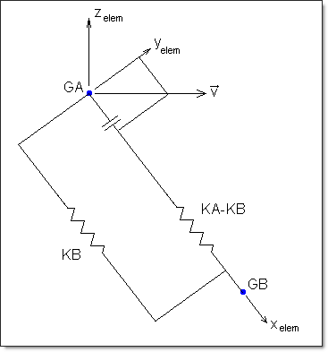
CGAP Element Coordinate System
| 10. | Refer to Small Displacement Nonlinear Analysis in the User's Guide for more information on using nonlinear gaps. |
| 11. | Heat transfer properties can be defined for Gap elements using the PGAPHT bulk data entry. |
| 12. | This card is represented as a gap or mass element in HyperMesh. |
See Also: