| 1. | Joints are defined by a spring and two local coordinate axes, which belong to connected bodies. Assume that the connected bodies are rigid to ensure the orthogonality of their local axes. Yet, deformable bodies may be connected with a joint, but a warning will be displayed by RADIOSS in this case; moreover if the axis becomes non-orthogonal during deformation, the stability of the joint cannot be insured. |
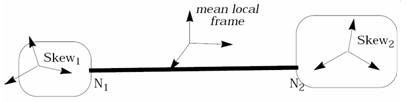
| 2. | Joint properties are defined in a local frame computed with respect to two connected coordinate systems. They do not need to be initially coincident. If the initial position of the local coordinate axis coincides at any time, the joint local frames are defined at a mean position. If the local axes' are not initially coincident, they are first transformed into a mean position between the initial state. Then the joint local frame will be computed with respect to these rotated axes. |
| 3. | Total number of joint DOF's computed in the local skew frame is six: |
| 4. | Blocked and free DOF's are distinguished for each joint type. |
| 5. | The blocked DOF's are characterized by a constant stiffness. |
| 6. | Selecting a high value with respect to the free DOF stiffness is recommended. The free DOF have user-defined characteristics, which can be linear or nonlinear elastic, combined with a sub-critical viscous damping. |
| 7. | The translational and rotational DOF are defined as follows: |
 , where dx1 and dx2 are total displacements of two joint nodes in the local coordinate system. , where dx1 and dx2 are total displacements of two joint nodes in the local coordinate system.
 , where , where  and and  are total relative rotations of two connected body axes, with respect to the local joint coordinate frame. are total relative rotations of two connected body axes, with respect to the local joint coordinate frame.
| 8. | Forces and moments calculation: |
| • | The force in direction  is computed as: is computed as: |
Linear spring:
Kt : translational stiffness 
Ct : translational viscosity 
Nonlinear spring:
| • | The moment in  direction is computed as: direction is computed as: |
Linear spring:
Kr: rotational stiffness (Krx, Kry, and Krz)
Cr: rotational viscosity (Crx, Cry, and Crz)
Nonlinear spring:
| • | The joint length may be, but is not necessarily equal to 0. It is recommended; however, to use a 0 length spring to define a spherical joint or an universal joint. |
| • | To satisfy the global balance of moments in a general case, correction terms in the rotational DOF are calculated as follows: |
Joint Types List
Type No.
|
Joint type
|
dx
|
dy
|
dz
|

|

|

|
1
|
Spherical
|
x
|
x
|
x
|
0
|
0
|
0
|
2
|
Revolute
|
x
|
x
|
x
|
0
|
x
|
x
|
3
|
Cylindrical
|
0
|
x
|
x
|
0
|
x
|
x
|
4
|
Planar
|
x
|
0
|
0
|
0
|
x
|
x
|
5
|
Universal
(development source only)
|
x
|
x
|
x
|
x
|
0
|
0
|
6
|
Translational
|
0
|
x
|
x
|
x
|
x
|
x
|
7
|
Oldham
|
x
|
0
|
0
|
x
|
x
|
x
|
8
|
Rigid
|
x
|
x
|
x
|
x
|
x
|
x
|
9
|
Free
|
0
|
0
|
0
|
0
|
0
|
0
|
where:
x: denotes a blocked DOF
0: denotes a free (user-defined) DOF
| • | Joints do not have user-defined mass or inertia, so the nodal time step is always used. |
| • | There are two ways to introduce viscous damping: |
1) Defining a critical damping (for blocked DOF only):
Viscous damping is defined in terms of the critical damping factor. The critical damping coefficient is calculated using the blocking stiffness value of the element. The mass and inertia are equal to half of the values of each rigid body connected to the joint. The approximation is then satisfactory, if only one joint is connected to each rigid body. Otherwise, the critical damping is over-estimated, in which case the damping factor in the RADIOSS input should be decreased. The same damping is applied to all blocked DOF.
2) User-defined constant or nonlinear damping:
It is possible to define independent damping parameters for each free DOF.
| 10. | If Skflag = 1, the joint local frame is chosen as the local coordinate system of the first connected body. In this case, a mean skew position is not calculated. However, the second local coordinate system must still be defined. |
| 11. | For a universal joint, this option is not active, and both skew axes are always used to calculate the local joint frame. |
| 12. | Coefficients Krx, Kry, Krz, Ktx, Kty, and Ktz are used for linear joint if there are no user-defined functions. If a function number in any DOF is not 0, the corresponding stiffness coefficient becomes a scale factor for the function. This rule is applied to any DOF of all joint types. |
| 13. | Coefficients Crx, Cry, Crz, Ctx, Cty, and Ctz are used as linear viscosity coefficients if there are no user-defined functions. If a function number in any DOF is not 0, the corresponding coefficient becomes a scale factor for the function. |
| 14. | The universal joint length must be equal to 0, in the initial state. The universal joint local skew system is defined as follows: |
Y local axis = X-axis of the first body local skew system
Z local axis = X-axis of the second body local skew system
X local axis = 
| 15. | This local frame must be initially orthogonal. The X-axis of two defining body skew axes must; therefore, be orthogonal in the initial position. The joint local frame can further become non-orthogonal due to deformation. The forces and moments are then computed in this non-orthogonal frame. |
| 16. | Each /PROP/KJOINT uses a unique definition of local coordinate system; therefore, one property can refer to only one spring element. |
|


