| 1. |  is the difference between the current length and the initial length of the spring element. is the difference between the current length and the initial length of the spring element. |
| 2. | In case of Ileng =0 (flag Ileng is defined in Line 3), the force in the spring is computed as: |
Linear spring:
Nonlinear spring:
with 
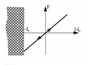
Linear spring
|
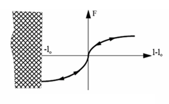
Nonlinear elastic spring, H1=0
|
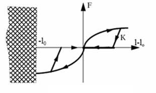
Nonlinear elastic plastic spring, H1=1
|
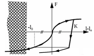
Nonlinear elasto-plastic spring with decoupled hardening in tension and compression, H1=2
|

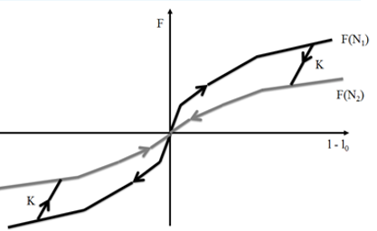
Nonlinear elasto-plastic spring with isotropic hardening and nonlinear unloading, H1=6
|
Nonlinear spring with elastic hystersis, H1=7
|
| 3. | If Ileng = 1, all input are per unit length: |
| • | Spring mass =  Spring stiffness = Spring stiffness =  Spring damping = Spring damping =  Spring inertia = Spring inertia =  |
Where, l0 is the spring reference length.
| • | The value of force in the spring is computed as: |
- Linear spring:
- Nonlinear spring:
Where,  is the engineering strain: is the engineering strain:

- Force functions are given versus engineering strain and engineering strain rate.
- Failure criteria are defined with respect to strain. Input of negative/positive failure limit should be related to initial length l0
| 4. | If  (resp (resp  ) is 0, no failure in the direction. The ) is 0, no failure in the direction. The  must be negative. For linear springs, must be negative. For linear springs,  and and  are null functions and A1, B1 and E1 are not taken into account. are null functions and A1, B1 and E1 are not taken into account. |
| 5. | Spring is activated and/or deactivated by sensor: |
| • | If sens_ID ≠ 0 and Isflag = 0, the spring element is activated by the sens_ID. |
| • | If sens_ID ≠ 0 and Isflag = 1, the spring element is deactivated by the sens_ID. |
| • | If sens_ID ≠ 0 and Isflag = 2, then: |
| • | The spring is activated and/or, deactivated by sens_ID.
(if sensor is ON, spring is ON; if sensor is OFF, spring is OFF). |
| • | The spring reference length (l0) is the distance between spring node N1 and N2 at the time of the sensor’s activation. |
| 6. | If a sensor is used for activating or deactivating a spring, the reference length of the spring at sensor activation (or deactivation) is equal to the nodal distance at time =0; except if sensor flag is equal to 2. |
| 8. | If fct_IDfr and Fric = 0 (no friction), then  . . |
| 9. | If fct_IDfr = 0 and Fric > 0, then constant Coulomb friction coefficient used:  |
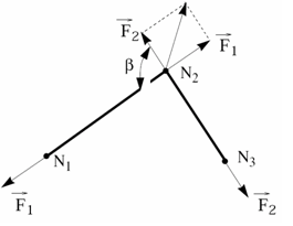
If fct_IDfr > 0, then variable friction is calculated as a function on relative force between two pulley branches:
Where,  is the angle (radians unit) and ffr is the function of fct_IDfr. is the angle (radians unit) and ffr is the function of fct_IDfr.
|


