MotionView User's Guide

Box Graphic

Box Graphic

Previous topic Next topic Expand/collapse all hidden text  

Box Graphic

Previous topic Next topic JavaScript is required for expanding text JavaScript is required for the print function  

This section describes the Box graphic entity of MotionView and shows the various usage, creation, and editing methods.

Theory/Background

There are three ways in which a Box graphic (or Cuboid) can be defined based on the location of the graphic reference frame about which graphic is being created.  The dimensions for the graphic are also specified using this reference frame.

hmtoggle_plus1Center

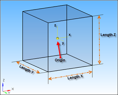
The Center Box Graphic has its origin of the reference frame about which the box is defined located at the geometrical center of the Box.

box_graphic_entity_center_diagram_mv

hmtoggle_plus1Corner

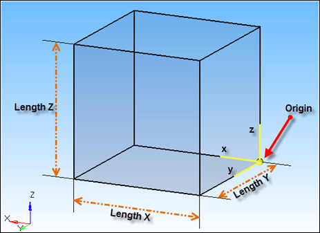
The Corner Box Graphic has the origin of the reference frame located at any one of the eight corners of the Box.

box_graphic_entity_corner_diagram_mv

hmtoggle_plus1Face Center

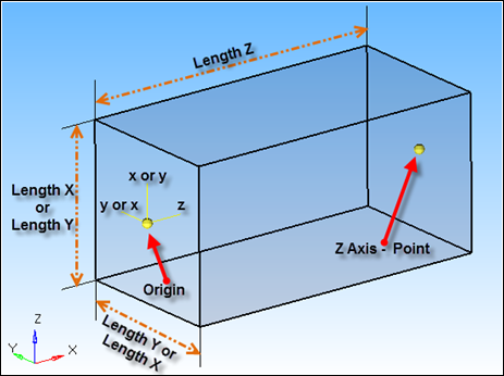
The Face Center Box Graphic has its origin located at the center of one of the faces.

box_graphic_entity_face_center_diagram_mv

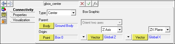
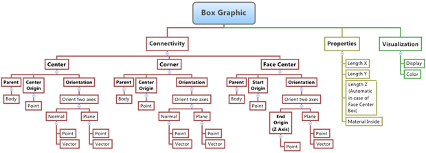
The figure below shows the various Box graphic options and settings that are available in MotionView:

box_graphic_entity_diagram_mv

Creating and Editing Box Graphics

To learn how to add a Box Graphic to a model, please see the Graphics topic.

hmtoggle_plus1To create/add a Box Graphic to a model:
1.Once an Box Graphic has been added to the model using any of the entity creation methods, the panel for the Box Graphic will be displayed in the panel area.

box_graphic_entity_center_panel_mv

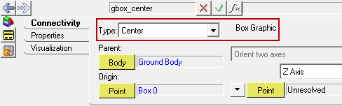
Graphics Panel - Connectivity Tab - Center Box Graphic - Single Entity

box_graphic_pair_entity_center_panel_mv

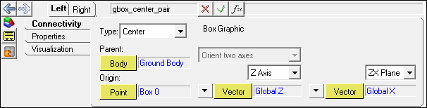
Graphics Panel - Connectivity Tab - Center Box Graphic - Pair Entity

2.From the Connectivity tab, use the Type drop-down menu to define a Center, Corner, or Face Center Box graphic.

box_graphic_entity_center_panel_type_options_mv

3.Click the Body collector (located under Parent) and select a body by picking the body from the graphics area, or double click the Body collector to open the model tree (from which the desired body can be selected).
4.Click the Point collector (located under Origin) and select a point by picking the point from the graphics area, or double click the Point collector to open the model tree (from which the desired point can be selected).
5.The reference frame (and thereby the graphic) for the three graphic types is oriented by specifying two of the three axes which follow from the standard Methods of Orientation.
-The Face Center box uses only one method from this standard method (Two AxesZX or ZY).  The Z axis is oriented by providing a point as a reference.
-To orient the reference frame (for Center and Corner Box only), choose the desired axis X, Y, or Z from the Axis pull down menu and define the axis using a Point or Vector collector.
-Choose the desired plane (XY, XZ, YX, YZ, ZX or ZY) from the Plane drop-down menu and define the plane using a Point or Vector collector.
6.The dimensions of the graphic are specified by providing values for LengthX, LengthY, and LengthZ.  Click the Properties tab and enter the dimensions of the Box graphic in the designated fields.

box_graphic_entity_panel_properties_tab_mv

-In the case of Face Center box, the LengthZ is automatically determined by the distance between the Origin and reference point for the Z axis (the two points that define the Z axis of reference frame).
-The graphic can be modeled as a Single or Pair entity. When modeled as a Pair entity, the joint will have symmetric properties about the ZX plane of the model.
7.If the graphic is used in Contacts, the Material inside option will determine the side from which the contact is detected.
-For contacts outside of the box, activate/check on this option.
-If the contact is to be detected from inside the box, deactivate/uncheck this option.
8.When defining a Pair Graphics, use pair entities for Body, Origin, etc.

Note - The same steps as shown above can also be used to define Pair Box Graphic entities.

Box Graphic in MDL and XML Formats

The model containing the Box Graphic can be saved in MDL format from MotionView and exported in the MotionSolve XML format.

hmtoggle_plus1Box Graphic in MDL (Model Definition Language)

The Box Graphic entity can be of the following types:

1.Center (Single or Pair)
2.Corner (Single or Pair)
3.Face Center (Single or Pair)

Syntax:

*Graphic(varname, label, BOX,

                       body,

                       CORNER|CENTER,

                       origin,

                       orient_plane,

                       align_type,

                       align_axis,

                       align_type,

                       align_plane,

                       length_x,

                       length_y

                       length_z)

Example:

*Graphic( gra_box_center, "Box Graphic  - Center", BOX,

                                                  B_Ground,

                                                  CENTER,

                                                  p_bmid0,

                                                  ZX,

                                                  VECTOR,

                                                  V_Global_Z,

                                                  VECTOR,

                                                  V_Global_X,

                                                  5000,

                                                  5000,

                                                  5000 )

Syntax:

*Graphic(varname, label, BOX,

                       body,

                       CORNER|CENTER,

                       origin,

                       orient_plane,

                       align_type,

                       align_axis,

                       align_type,

                       align_plane,

                       length_x,

                       length_y

                       length_z)

Example:

*Graphic( gra_box_corn, "Box Graphic - Corner", BOX,

                                               B_Ground,

                                               CORNER,

                                               p_b2,

                                               ZX,

                                               VECTOR,

                                               V_Global_Z,

                                               VECTOR,

                                               V_Global_X,

                                               1000,

                                               5000,

                                               5000 )

Syntax:

*Graphic(varname, label, BOX,

                       body,

                       FACE,

                       end_1,

                       orient_plane,

                       end_2,

                       align_type,

                       align_plane,

                       length_x,

                       length_y)

Example:

*Graphic( gra_box_face, "Box Graphic - Face Center", BOX,

                                                    B_Ground,

                                                    FACE,

                                                    p_b1,

                                                    ZX,

                                                    p_b2,

                                                    VECTOR,

                                                    V_Global_X,

                                                    3000,

                                                    3000 )

Syntax:

*GraphicPair(varname, label, BOX,

                       body,

                       CORNER|CENTER,

                       origin,

                       orient_plane,

                       align_type,

                       align_axis,

                       align_type,

                       align_plane,

                       length_x,

                       length_y

                       length_z)

Syntax:

*GraphicPair(varname, label, BOX,

                       body,

                       FACE,

                       end_1,

                       orient_plane,

                       end_2,

                       align_type,

                       align_plane,

                       length_x,

                       length_y)

To understand the complete syntax of the MDL statements mentioned above, please refer to the following MotionView MDL Reference Guide topics: *Graphic() - box*GraphicPair() - box pair*DefineGraphic().

hmtoggle_plus1Box Graphic in XML Format

The Box Graphic when exported to the MotionSolve XML format is exported as a Post_Graphic statement.

Syntax:

<Post_Graphic

      id                 = "integer"

      type               = "BoxDefinedFromCorner"

      corner_marker_id   = "integer"

      length_x           = "real"

      length_y           = "real"

      length_z           = "real"

      is_material_inside = {TRUE, FALSE}

</Post_Graphic>


<Post_Graphic

      id                 = "integer"

      type               = "BoxDefinedFromCenter"

      center_marker_id   = "integer"

      length_x           = "real"

      length_y           = "real"

      length_z           = "real"

      is_material_inside = { "TRUE" | "FALSE" }

</Post_Graphic>

In case of the Box Graphic the model statement will be as shown below:

<Post_Graphic

  id                  = "90002"

  type                = "BoxDefinedFromCorner"

  corner_marker_id    = "90000002"

  length_x            = "1000."

  length_y            = "500."

  length_z            = "1000."

  is_material_inside  = "TRUE"

/>


<Post_Graphic

  id                  = "90001"

  type                = "BoxDefinedFromCenter"

  center_marker_id    = "90000001"

  length_x            = "300."

  length_y            = "300."

  length_z            = "2382.9047"

  is_material_inside  = "TRUE"

/>

To understand the complete syntax of the Post_Graphic XML model statement, please refer to the MotionSolve Reference Guide topic for Post_Graphic.

Creating and Editing Box Graphics using Tcl

In MotionView, Tcl can be used to add any MDL entities to the model.  There are two Tcl commands that can be used to add an entity:

hmtoggle_arrow1InterpretEntity

Syntax:

mdlmodel_handle InterpretEntity new_handle keyword varname label

In case of the Box Graphic the statement will look as shown below:

mdlmodel_handle InterpretEntity gra Graphic gra_box_center "\"Box Graphic  - Center\"" BOX  B_Ground CENTER p_bmid0 ZX VECTOR V_Global_Z VECTOR V_Global_X 5000 5000 5000;

hmtoggle_arrow1InterpretSet

*This command is not applicable for Graphic entities.

The InterpretEntity command is used to add entities to the model and the InterpretSet command is used to set the entity properties.  To understand the complete usage and syntax of these commands, please refer to the InterpretEntity and InterpretSet topics located within the HyperWorks Desktop Reference Guide.

Note - When using the InterpretEntity and InterpretSet commands, it is important to also use the Evaluate command in order for the changes to take effect immediately.

To learn how to create a complete model using Tcl commands, please refer to tutorial MV-1040: Model Building Using Tcl.

Example Model

The following example shows all of the Box Graphic entities:

hmtoggle_plus1Box.mdl

*BeginMDL( the_model, "Model", "12.0.0.85" )

 *StandardInclude(FILE)

 *SetCurrentSolverMode(MotionSolve)

 *Point( p_a, "Point A" )

 *Point( p_b, "Point B" )

 *Point( p_c, "Point C" )

 *PointPair( p_d, "Point D" )

 *PointPair( p_e, "Point E" )

 *PointPair( p_f, "Point F" )

 *Point( p_g, "Point G" )

 *SetPoint( p_g,                        30.0, 0.0, 0.0 )

 *PointPair( p_h, "Point H" )

 *SetPoint( p_e,                  LEFT, 75.0, 20.0, 0.0 )

 *SetPoint( p_h,                  LEFT, 85.0, 20.0, 0.0 )

 *SetPoint( p_b,                        20.0, 0.0, 0.0 )

 *SetPoint( p_c,                        40.0, 0.0, 0.0 )

 *SetPoint( p_d,                  LEFT, 60.0, 20.0, 0.0 )

 *SetPoint( p_f,                  LEFT, 100.0, 20.0, 0.0 )

 *Body( b_a, "Body A", p_a, , , ,  )

 *Body( b_b, "Body B", p_b, , , ,  )

 *Body( b_c, "Body C", p_c, , , ,  )

 *BodyPair( b_d, "Body D", p_d, , , ,  )

 *BodyPair( b_e, "Body E", p_e, , , ,  )

 *BodyPair( b_f, "Body F", p_f, , , ,  )

 *Set( b_a.usecm, true )

 *Set( b_b.usecm, true )

 *Set( b_c.usecm, true )

 *Set( b_d.usecm, true )

 *Set( b_e.usecm, true )

 *Set( b_f.usecm, true )


#Example for a Single Center Box Graphic

 *Graphic( gbox_singCenter, "Box Graphic Single - Center", BOX, b_a, CENTER, p_a, ZX, POINT, p_b, VECTOR, V_Global_X, 10.0, 10.0, 10.0 )


#Example for a Single Face Center Box Graphic

 *Graphic( gbox_singfaceCenter, "Box Graphic Single - Face Center", BOX, b_b, FACE, p_b, ZX, p_g, VECTOR, V_Global_X, 10.0, 10.0 )


#Example for a Single Corner Box Graphic

 *Graphic( gbox_singcorner, "Box Graphic Single - Corner", BOX, b_c, CORNER, p_c, ZX, POINT, p_d.l, VECTOR, V_Global_X, 10.0, 10.0, 10.0 )


#Example for a Pair Center Box Graphic

 *GraphicPair( gbox_pariCenter, "Box Graphic Pair - Center", BOX, b_d, CENTER, p_d, ZX, POINT, p_e, VECTOR, V_Global_X, 10.0, 10.0, 10.0 )


#Example for a Pair Face Center Box Graphic

 *GraphicPair( gbox_pairfaceCenter, "Box Graphic Pair - Face Center", BOX, b_e, FACE, p_e, ZX, p_h, VECTOR, V_Global_X, 10.0, 10.0 )


#Example for a Pair Corner Box Graphic

 *GraphicPair( gbox_paircorner, "Box Graphic Pair - Corner", BOX, b_f, CORNER, p_f, ZX, POINT, p_a, VECTOR, V_Global_X, 10.0, 10.0, 10.0 )

*EndMDL()


See Also:

Graphic Entity Attributes Panel

Adding and Removing Entities

*Graphic() - box (MDL Model Statement)

*GraphicPair() - box pair (MDL Model Statement)

*DefineGraphic() (MDL Model Statement)

Post_Graphic (XML Command)

InterpretEntity (Tcl Command)

InterpretSet (Tcl Command)