MotionView User's Guide

File Graphic

File Graphic

Previous topic Next topic Expand/collapse all hidden text  

File Graphic

Previous topic Next topic JavaScript is required for expanding text JavaScript is required for the print function  

This section describes the File graphic entity of MotionView and shows the various usage, creation, and editing methods.

Theory/Background

The File graphic type is used when realistic shapes of the bodies of the mechanism are to be included in the model.  File graphics can be imported into MotionView using the Import CAD or FE Utility, or if an H3D file of the CAD data already exists then it can be manually added (using the method described below).  Other file formats that are supported include: .g, .shl, and .obj.

file_graphic_example_mv

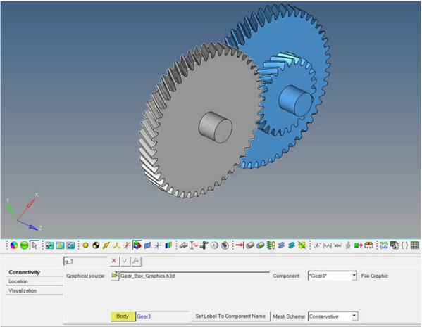
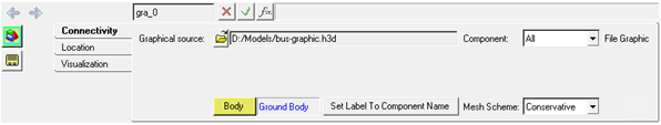
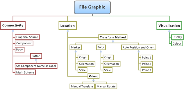
The figure below shows the various File graphic options and settings that are available in MotionView:

file_graphic_diagram_mv

Creating and Editing File Graphics

To learn how to add a File graphic to a model, please see the Graphics topic.

hmtoggle_plus1To create/add a File graphic to a model:
1.Once an File Graphic has been added to the model using any of the entity creation methods, the panel for the File Graphic will be displayed in the panel area.

file_graphic_panel_connectivity_tab_mv

Graphics Panel - Connectivity Tab - Center Box Graphic - Single Entity

Note - A File graphic cannot be defined as a Pair Entity.  It can only be defined as a single entity.

2.To assign this graphic to a body in the model, click the Body collector and select a body by picking the body from the graphics area, or double click the Body collector to open the model tree (from which the desired body can be selected).
3.Use the Component drop-down menu (located in the top right corner of the panel) to select All or the desired component name.
4.Click the Set Label Label to Component Name button to set the component name as the label of the graphic entity.
5.Use the Mesh Scheme drop-down menu to select a desired mesh coarsening level for the graphic entity:

Aggressive

the highest level of coarsening applied

Average

an intermediate level of coarsening is applied.

Conservative

an intermediate level of coarsening is applied.

None

no coarsening is applied

When the MotionView model is exported to MotionSolve, the file graphic information is written as a triangular mesh with nodes and elements (tessellation).  A fine mesh on the surfaces results in a large amount of nodes and elements in the MotionSolve XML file and subsequently a larger size MotionSolve results animation file.  The Mesh Scheme setting provides a way to coarsen the mesh upon export, thus reducing the file size of the XML as much as possible.

Note - If the graphic is used in Contact modeling, a Mesh Scheme of None is recommended.

6.If the Imported H3D file graphic is not positioned/oriented in the desired fashion in the model reference frame, this can be corrected using the options available on the Location tab.

file_graphic_panel_location_tab_mv

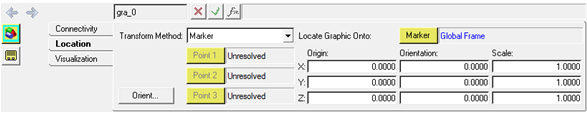
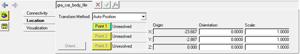
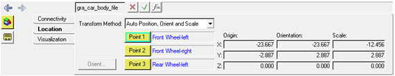
File Type Graphics Panel – Location Tab

7.From the Location tab, select one of the following transformation methods from the Transform Method drop-down menu:
8.To position a File Graphic using the Marker method, select Marker from the Transform Method drop-down menu.
9.Click the Marker collector and select the  Marker that you want to use as a Reference Marker for transformation.  By default the Global Frame is set as the reference marker.
10.If you know the absolute values of the position and orientation of the graphic with respect to the chosen Reference Marker, enter those values in the X, Y, Z fields (located under Origin) and the three Euler angles (in radians) in the three Orientation fields.
11.The graphic can also be scaled by entering the scale factor in the three directions of the Reference Marker into the fields located under Scale.
12.If you do not know the absolute values of position and orientation you can incrementally move and rotate the graphic using the Graphic Orient option.  Click the Orient button to invoke the Graphic Orient dialog.

file_graphic_graphic_orient_dialog_mv

13.Enter the desired translational displacement values in the fields labeled Translate (for any or all of the three translational axes) by clicking the appropriate check box to select the same.  Click the + or buttons for the graphic to be moved accordingly.
14.To apply rotations you will need to apply rotations one axis at a time.  In the fields labeled Rotate, click the desired radio button for RX, RY, or RZ and enter the desired rotation value in degrees. Click the + or buttons to apply the rotation.

Repeat the same process for the other two rotational axes if required.

15.After applying the translations and rotations click OK.  The entered values will now be applied to the graphic and will be displayed on the panel.
16.You can repeat using the Graphic Orient dialog until the graphic has been moved to the desired position and orientation.
8.To use the second transformation method, select Body from the Transform Method drop-down menu. This method is used to specify the location and orientation with respect to the Center of Mass marker of any Body instead of an explicit marker.
9.Click the Body collector labeled Locate Graphic Onto: and pick the body to be used as a reference for specifying the location and orientation for the File graphic.
10.The steps 3 to 11 apply for this transform method as well.

Note - If the CAD or FE Import utility was used to import the graphic into the model and if Locator Points were created to specify the three points on the Graphic, then three additional transform methods are available:

Auto Position
Auto Position and Orient
Auto Position, Orient and Scale.

As the names suggest the three methods use the three locator points to Position and Orient and/or scale the imported File graphic.

8.Select the desired Auto Positioning option from the Transform Method: pull down menu and the top most Point collector button will be activated.
9.Click the Point collector and pick a point from the graphics area that represents the position of the file graphic.

file_graphic_panel_location_tab_auto_position_mv

File Graphic – Location Tab – Auto Position Option

10.Enter the Orientation and Scale values for the file graphic in the fields labeled Orientation: and Scale: respectively.
8.To use the method Auto Position and Orient select the same from the Transform Method: pull down menu.

For this method the Point 1 and Point 2 collectors will get activated.

9.Select a point that represents Orientation of the Graphic for Point 2 collector.
10.Enter three scale values in the fields labeled Scale.
8.To use the method Auto Position, Orient and Scale select the same from the Transform Method: pull down menu.
9.Now all three buttons Point 1, Point 2, and Point 3 will be activated.
10.Select the three points that represent the Position, Orientation and Scale of the file graphic and the graphic will be automatically moved to desired location with proper orientation and scale.

file_graphic_panel_location_tab_auto_pos_orient_scale_mv

File Graphic – Auto Position, Orient and Scale

hmtoggle_plus1To generate an H3D Graphic File from HyperMesh:

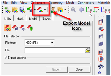
Altair HyperMesh can be used to generate H3D graphics for use in MotionView. HyperMesh allows of export of FE models and 3D CAD models as H3D files. This option is available in the Export Model option of HyperMesh.

1.In HyperMesh go to File>Export>Model to use this option.

file_graphic_hm_example_mv

Export H3D File from HyperMesh

HyperMesh provides two File Type options for exporting HyperMesh models into H3D format:

Exporting the Finite Element Model as H3D
Export the Geometry (Surfaces) in the Model to H3D
2.Select H3D (FE) or H3D (Geometry) from the File type drop-down menu  (shown in the image above).

The H3D (FE) option converts the FE Mesh into tessellated surface and exports the same as an H3D file, while the H3D (Geometry) option converts the geometrical surfaces in the model into tessellated surface and exports the same as an H3D file.  

File Graphic in MDL and XML Formats

The model containing the File Graphic can be saved in MDL format from MotionView and exported in the MotionSolve XML format.

hmtoggle_plus1File Graphic in MDL (Model Definition Language)

The file graphic information is saved in MDL with the below syntax.

Syntax:

*Graphic(gr_name, "gr_label", FILE,

                            body,

                            "file_name",

                            {"component1", "component2", ..."componentN"},

                            [GLOBAL/PART/MARKER/AUTO_POS/AUTO_POS_ORIENT/AUTO_POS_ORIENT_SCALE],

                            [ref_body/ref_marker],

                            [x], [y], [z],

                            [psi], [theta], [phi],

                            [scale_x], [scale_y], [scale_z])

Example:

*Graphic( gra_file, "Bus Graphic - File", FILE,

                                         b_busbody,

                                         "D:/Models/bus-graphic.h3d",

                                         {},

                                         PART, ,

                                         1, 0.0, 0.0,

                                         0.0, 0.0, 0.0,

                                         1000, 1000, 1000 )

To understand the complete syntax of the MDL statement mentioned above, please refer to the *Graphic() - file topic located in the MotionView MDL Reference Guide.

hmtoggle_plus1File Graphic in XML Format

The File Graphic when exported to the MotionSolve XML format is exported as a Post_Graphic statement.

Syntax:

<Post_Graphic

      id                 = "integer"

      type               = "TRIAMESH"

      ref_marker_id      = "integer"

      num_triangle       = "integer" >

! Vertex data

real     real     real     real     real     real     real     real     real

...      ...      ...      ...      ...      ...      ...      ...      ...

real     real     real     real     real     real     real     real     real

</Post_Graphic>

In case of the File Graphic the model statement will be as shown below:

 <Post_Graphic

    id                  = "90006"

    color               = "158:200:23"

    type                = "TriaMesh"

    ref_marker_id       = "90000005"

    num_point           = "76482"

    num_triangle        = "151177">

<!-- Node Position -->

-2.1779639E3 -1.5064539 2.8792861E3 -2.1774028E3 6.3421154E1 2.8284861E3 -2.1773882E3 -6.4252182E1 2.8284861E3

-2.1761772E3 3.4806011E1 1.297479E3 -2.1759766E3 -5.222319E1 1.297658E3 -2.1759707E3 1.1951136E2 2.8792861E3

-2.1759421E3 1.1843014 1.2991571E3 -2.1758689E3 -1.2252312E2 2.8792861E3 -2.1748318E3 -1.0383035E2 1.2995461E3

-2.1746892E3 1.1835222 1.3005366E3 -2.1744487E3 1.0616689E2 1.3004889E3 -2.1743638E3 1.2207528E2 1.2990962E3

-2.1742458E3 6.4930302E-1 1.2537863E3 -2.1739795E3 -1.0376627E2 1.3012019E3 -2.1739136E3 1.0613245E2 1.3012607E3

.

.

 </Post_Graphic>

To understand the complete syntax of the Post_Graphic XML model statement, please refer to the MotionSolve Reference Guide topic for Post_Graphic.

Creating and Editing File Graphics using Tcl

In MotionView, Tcl can be used to add any MDL entities to the model.  There are two Tcl commands that can be used to add an entity:

hmtoggle_arrow1InterpretEntity

Syntax:

mdlmodel_handle InterpretEntity new_handle keyword varname label tokens

hmtoggle_arrow1InterpretSet

*This command is not applicable for Graphic entities.

The InterpretEntity command is used to add entities to the model and the InterpretSet command is used to set the entity properties.  To understand the complete usage and syntax of these commands, please refer to the InterpretEntity and InterpretSet topics located within the HyperWorks Desktop Reference Guide.

Note - When using the InterpretEntity and InterpretSet commands, it is important to also use the Evaluate command in order for the changes to take effect immediately.

To learn how to create a complete model using Tcl commands, please refer to tutorial MV-1040: Model Building Using Tcl.

Example Model

The following example shows the File Graphic entity:

hmtoggle_plus1File.mdl

*BeginMDL( the_model, "Model", "12.0.0.85" )

 *StandardInclude(FILE)

 *SetCurrentSolverMode(MotionSolve)

 *Point( p_0, "Point 0" )

 *Body( b_0, "Body 0", p_0, , , ,  )

 *Point( p_1, "Point 1" )


#Example for a File Graphic – To use the Graphic File given here, please change the file path to Altair Installation Folder path.

 *Graphic( gfile_0, "FileGraphic 0", FILE, b_0, "C:/Program Files/Altair/12.0/demos/mv_hv_hg/animation/h3d/NEON_FRONT.h3d", {}, PART, b_0, 0.0, 0.0, 0.0, 0.0, 0.0, 0.0, 1.0, 1.0, 1.0 )

 *Set( b_0.usecm, true )

 *SetPoint( p_1,                        1000.0, 0.0, 0.0 )

*EndMDL()

See Also:

Graphic Entity Attributes Panel

Adding and Removing Entities

*Graphic() - file (MDL Model Statement)

*DefineGraphic() (MDL Model Statement)

Post_Graphic (XML Command)

InterpretEntity (Tcl Command)

InterpretSet (Tcl Command)