This topic describes the Graphic Entity attributes in MotionView and shows the various usage, creation, and editing methods.
Theory/Background
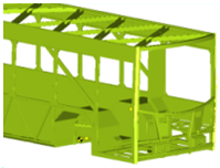
Controlling the display of the entities in the model during pre-processing of the model is essential, as it leads to ease of modeling and identification of the entities being modeled. The two main types of graphics displayed in MotionView are shown in the figure below:
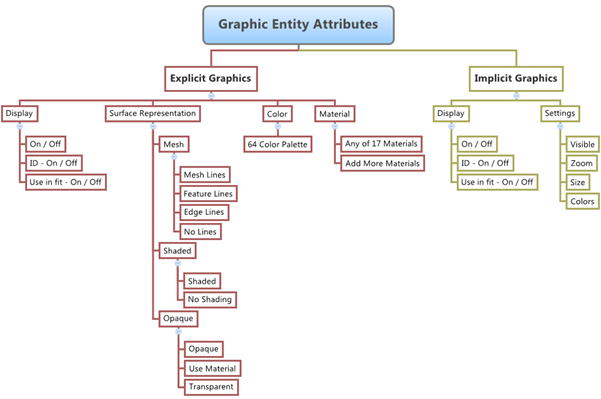
Explicit Graphics
Explicit Graphics are those which can be created from the Graphics panel in MotionView. These graphics are associated with entities like Bodies, Beams, etc. and are also available for display during the post-processing of simulation results.
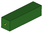
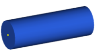
Examples of Explicit Graphics are shown below:
Implicit Graphics
An Implicit graphic is an auto-generated graphical representation of each entity created in MotionView. These graphics are associated with almost all entities.
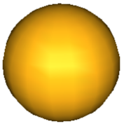
Examples of Implicit Graphics are shown below:

Point
|

Body
|

Ball Joint
|

Force
|
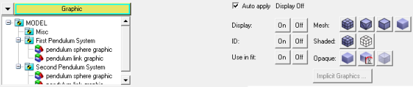
The Graphic Entity Attributes panel can be used to control the display of the graphics in the model (both explicit, as well as implicit).
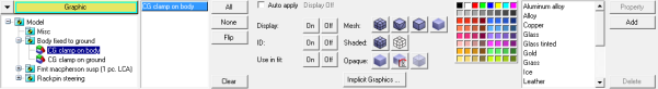
Graphics Entity Attributes Panel
The settings applicable for explicit graphics are different from those available for implicit graphics.
Supported Entities
The graphical attributes for various types of entities can be controlled in MotionView. The default entity is Graphic, however other categories can be selected by using the Category drop-down menu (see the table below):
Entity Type
|
Applicable Graphic Attributes
|
Graphics
|
Explicit Only
|
Body
|
Both Explicit and Implicit
|
Spring Damper
|
Both Explicit and Implicit
|
Beam
|
Both Explicit and Implicit
|
Polybeam
|
Both Explicit and Implicit
|
Advanced Joint
|
Both Explicit and Implicit
|
Joint
|
Implicit Only
|
Point
|
Implicit Only
|
Vector
|
Implicit Only
|
Marker
|
Implicit Only
|
Coupler
|
Implicit Only
|
Motion
|
Implicit Only
|
Bush
|
Implicit Only
|
Force
|
Implicit Only
|
It is important to note that while the Graphics entity does not have any Implicit graphics associated with it, other entities (such as Body, Spring Damper, Beam, Polybeam, and Advanced Joint) may have both Explicit graphics and Implicit graphics associated with them. The remaining entities in the list above will only have Implicit graphics associated with them.
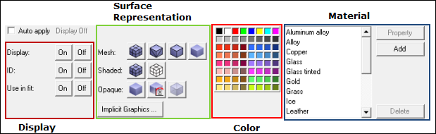
Graphic Attributes
The Graphic Entity Attributes panel is used to control the display of both Explicit and Implicit graphics in the model:
Explicit Graphics
The Attributes of Explicit Graphics that can be managed in the Graphics Entity Attributes panel can be grouped into four categories:
Click on the groups below to view the attributes for each group in detail:
Attribute Name
|
Icons
|
Description
|
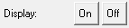
Display
|
|
Used to turn show or hide the selected graphic in the graphics area.
|
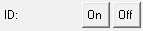
ID
|
|
Used to show or hide the ID (Label) of the graphic in the graphics area.
|
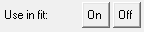
Use in fit
|
|
Used to specify if the selected graphic is to be included in the graphics area when the Fit Model/Fit All Frames  button is pressed. button is pressed.
|
|
Attribute Name
|
Icons
|
Description
|
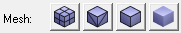
Mesh
|
|
Used to control the display of the surface mesh of the graphics. These buttons control display of:
Mesh Lines 
Feature Lines 
Edge Lines 
No Lines 
|
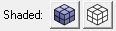
Shaded
|
|
Used to control the display of the surface shading of the graphics. These buttons control display of surfaces in the following modes:
Shaded
No Shading 
(wire frame)
|
Opaque
|
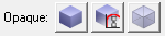
|
Used to control the opacity of the surfaces of the graphics. These buttons control display of surfaces in the following modes:
Opaque
Use material 
Transparent 
|
|
Attribute Name
|
Icons
|
Description
|
Color
|
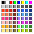
|
The Color of the graphic can be controlled using the 64 color palette provided on the panel.
|
|
Attribute Name
|
Icons
|
Description
|
Material
|
|
Used to apply a Material type for the surface of the selected graphic.
Note - This is only used for display purposes and does not apply FEM like material properties to the Bodies or entities in the model.
|
|
Implicit Graphics
The Implicit Graphics Settings dialog can be used to change the settings for the Implicit graphics in the model:
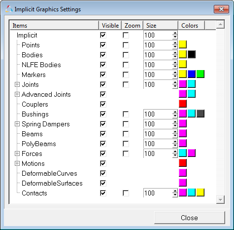
Implicit Graphics Settings Dialog
The following settings can be changed for Implicit graphics:
Turn on or off the visibility of the implicit graphic.
|
Turn on or off Zoom View of the implicit graphic. The default setting is Off.
|
Set the display size of the implicit graphic.
|
Change the colors of the implicit graphic. In some cases an implicit graphic can have multiple colors.
|
Apply Modes – Normal and Auto Apply
When specifying the graphics settings using the Graphic Entity Attributes panel there are two Apply modes available to the users:
| • | Normal - is generally applicable to all of the graphics attributes. |
Graphic Entity Attributes Panel in Normal Mode
| • | Auto Apply - is applicable only to the Display and Surface Representation attribute groups that are described above. |
Graphic Entity Attributes Panel in Auto Apply Mode
Entity Selection
To change the Graphic Attributes of an entity, it first has to be selected in the graphics area or in the Graphics Attributes Panel model tree.
| 1. | Click the Graphics Entity Attributes panel icon  on the General Actions toolbar, and then click on the Graphic that is visible in the graphics area. on the General Actions toolbar, and then click on the Graphic that is visible in the graphics area. |
OR
| 2. | Use the Model Tree on the Graphic Attributes Panel to select the entity (shown in the figure below). |
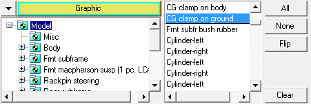
Model Entity Tree View for Selection
| 3. | To select entities in the Main Model, click the Model label in the Entity Tree View, and then select the entity from the entity list that is displayed next to the Entity Tree View. |
| 4. | Use the All, None, Flip or Clear buttons to modify the selection. |
|
Applying Entity Attributes
Once an entity is selected using one of the Entity selection methods described above, click the chosen graphic attribute settings buttons on the panel to change the attributes. The Attributes and their descriptions are mentioned in the table above.
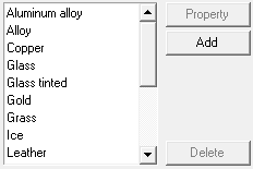
Surface Material Properties
The pre-configured material types that can be applied to the graphics in MotionView are:
The properties of these materials can be changed to suite special requirements.
| 1. | Select the desired material from the list (Aluminum Alloy, Alloy, Copper, etc.). |
| 2. | Click the Property button  . . |
The Material Properties dialog is displayed.
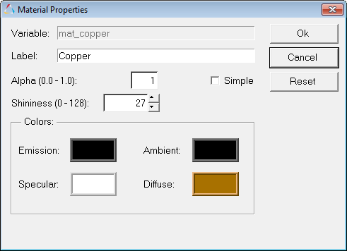
| 3. | Change any of the following Property settings: |
| 4. | Click Ok to apply the new Property settings and close the dialog. |
OR
| - | Click Cancel to cancel the operation and exit the dialog. |
OR
| - | Click Reset to restore the default values for the material properties. |
|
Changing Implicit Graphics Settings
The settings for the Implicit graphics in the model can be changed using the Implicit Graphics Settings dialog.
| 1. | From the Graphic Entity Attributes panel, click the Implicit Graphics button 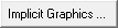 (located on the bottom middle portion of the panel). (located on the bottom middle portion of the panel). |
The Implicit Graphics Settings dialog is displayed.
Implicit Graphics Settings Dialog
|
Graphic Attribute Settings in the Project Browser
Some of the graphic entity attributes can also be changed from the Project Browser. You can use the buttons under the Color and Mesh columns to change the graphic attributes of the respective entity (see the image below):
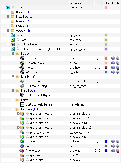
Project Browser Tree
| 1. | To change the color of an entity, right-click on the Color icon  for the desired entity (located under the Color column). for the desired entity (located under the Color column). |
The Colors/Materials dialog is displayed.
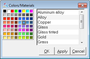
| 2. | Select a color (from the color palette) or a material (from the materials list) to be applied to the Graphic. |
| 3. | Click OK to apply the color/material and close the dialog. |
OR
| - | Click Apply to apply the color/material and keep the dialog open. |
OR
| - | Click Cancel to cancel the operation and exit the dialog. |
| 4. | To change the Mesh style of an entity, right-click on the Mesh icon  (located under the Mesh column). (located under the Mesh column). |
The Mesh/Shade dialog is displayed.
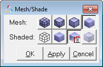
| 5. | Select the required mesh/shade style to be applied to the Graphic. |
| 6. | Click OK to apply the mesh/shade and close the dialog. |
OR
| - | Click Apply to apply the mesh/shade and keep the dialog open. |
OR
| - | Click Cancel to cancel the operation and exit the dialog. |
|
See Also:
Graphic Entity Attributes Panel
Adding and Removing Entities