The Orientation tab allows you to orient the elements of the NLFE Beam. This tab provides the ability to orient the beam differently between the start and the end of the beam. The Orientation tab is not applicable to Cable elements.
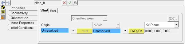
NLFE Body panel - Orientation tab
The NLFE beam has two markers available at each end; a Start Orientation and End Orientation Marker to assist with orienting the cross section.
The X-Axis of these two markers, by default, will be pointing along the length of the beam profile and hence is grayed out. The X axis of the Start Orientation marker is aligned with the second point defined in the beam profile, while that of the End Orientation marker is aligned along the vector formed by the last but one point and the last point in the beam profile.
The YZ plane of these two markers form the plane of the cross section. The Y-axis or Z-axis can be specified by using the XY|ZX Plane option in the panel.
The method of orientation is similar to that of orienting a Marker entity. Refer to Method of Orientation – Orient Two Axis to learn more.
Orientation Example:
The image below provides an example of orienting the beam cross-section. Each end of the beam is oriented differently, thereby inducing a twist in the beam profile.
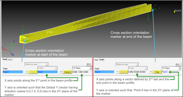
NLFE Body - Orientating the cross-section
See Also
*SetOrientation() (MDL Statement)


