The NLFE Body panel allows you to add a nonlinear finite element (Non Linear Finite Element) body to your MotionView model. This entity is only available in the MotionSolve solvermode.
Overview
NLFE stands for Non Linear Finite Elements. The NLFE implementation in MotionView/MotionSolve is based on Absolute Nodal Coordinate Formulation or ANCF. In this approach, only absolute coordinates and global slopes are used to define the element nodal coordinates without the need for using infinitesimal or finite rotations.
Benefits of Using NLFE
In complex Multi-Body Simulations, flexible bodies are needed to improve model fidelity. In cases where the deformations and rotations are expected to be large and/or exceed linear assumptions, NLFE becomes a necessity. NLFE can be employed in many application such as: cables, belt drives, leaf springs, twist beams, stabilizer bars, coil springs, and many more.
In addition to this, the application of NLFE does not need a reduction analysis to be performed before being used in a model. Also, the implementation is simple enough to enable the user to model sub-systems much faster than traditional FE methods. All of this reduces the model-solution turnaround time.
NLFE Implementation in MotionView
In MotionView version 14.0, 1D element or elements with two nodes are supported. The interface is simple to use and currently supports two types of elements: Beam and Cable. Eighteen standard cross-sections are made available for the BEAM in sync with OptiStruct PBEAML card.
The cross-sections available for Beam type are:
| Note | Multiple ways of defining a Box, C, I, and T sections are available. |
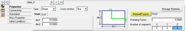
NLFE Body panel - Beam
A Cable can have a cross-section defined by its radius.
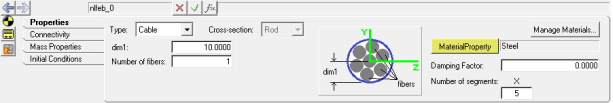
NLFE Body panel - Cable
Options are provided to define the pre-loaded positions. This is particularly useful when the model position and the ‘free-free’ position of a body are different. The best example for this would be a coil spring or a leaf spring in a vehicle suspension, which is modeled at design load.
A set of example material properties is made available. You can also add your own material property and save it in the model. An NLFE body can have the following material properties assigned to them:
The longitudinal profile of the NLFE beam or cable is defined using a sequence of points. Simply select a few points in the model or browse to a .CSV file to define the profile of the NLFE body.
| Note | It is recommended to solve the models with an NLFE body with a solver integrator max order < = 2. See the Simulation Settings dialog in the Run Solver panel. |
The NLFE panel contains the following tabs:
Properties
Connectivity
Orientation
Mass Properties
Initial Conditions
See Also
MotionSolve User's Guide
Body_Flexible (MotionSolve XML Command)
NLFE MotionSolve Statements


