Option
|
Description
|
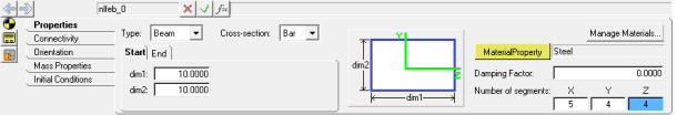
Type
|
Select the type of elements in the body. Options available are: Beam and Cable.
|
|
The following options are available if Beam is selected:
|
|
Bar 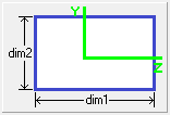
|
dim1 (Start/End) - Specify the edge dimension shown in the diagram for the cross-section at the start and end.
dim2 (Start/End) - Specify the edge dimension shown in the diagram for the cross-section at the start and end.
|
|
Box 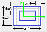
|
dim1 (Start/End) - Specify the outer edge dimension shown in the diagram for the cross-section at the start and end.
dim2 (Start/End) - Specify the outer edge dimension shown in the diagram for the cross-section at the start and end.
dim3 (Start/End) - Specify the wall thickness shown in the diagram for the cross-section at the start and end.
dim4 (Start/End) - Specify the wall thickness shown in the diagram for the cross-section at the start and end.
|
|
Box1 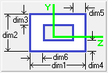
|
dim1 (Start/End) - Specify the outer edge dimension shown in the diagram for the cross-section at the start and end.
dim2 (Start/End) - Specify the outer edge dimension shown in the diagram for the cross-section at the start and end.
dim3 (Start/End) - Specify the wall thickness shown in the diagram for the cross-section at the start and end.
dim4 (Start/End) - Specify the wall thickness shown in the diagram for the cross-section at the start and end.
dim5 (Start/End) - Specify the wall thickness shown in the diagram for the cross-section at the start and end.
dim6 (Start/End) - Specify the wall thickness shown in the diagram for the cross-section at the start and end.
|
|
Chan 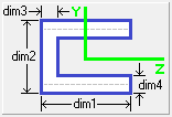
|
dim1 (Start/End) - Specify the edge dimension shown in the diagram for the cross-section at the start and end.
dim2 (Start/End) - Specify the edge dimension shown in the diagram for the cross-section at the start and end.
dim3 (Start/End) - Specify the wall thickness shown in the diagram for the cross-section at the start and end.
dim4 (Start/End) - Specify the wall thickness shown in the diagram for the cross-section at the start and end.
|
|
Chan1 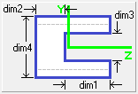
|
dim1 (Start/End) - Specify the depth dimension shown in the diagram for the cross-section at the start and end.
dim2 (Start/End) - Specify the wall thickness shown in the diagram for the cross-section at the start and end.
dim3 (Start/End) - Specify the slot height shown in the diagram for the cross-section at the start and end.
dim4 (Start/End) - Specify the edge dimension shown in the diagram for the cross-section at the start and end.
|
|
Chan2 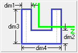
|
dim1 (Start/End) - Specify the wall thickness shown in the diagram for the cross-section at the start and end.
dim2 (Start/End) - Specify the wall thickness shown in the diagram for the cross-section at the start and end.
dim3 (Start/End) - Specify the edge dimension shown in the diagram for the cross-section at the start and end.
dim4 (Start/End) - Specify the edge dimension shown in the diagram for the cross-section at the start and end.
|
|
Cross 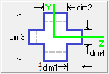
|
dim1 (Start/End) - Specify the cumulative web height shown in the diagram for the cross-section at the start and end.
dim2 (Start/End) - Specify the web thickness shown in the diagram for the cross-section at the start and end.
dim3 (Start/End) - Specify the height shown in the diagram for the cross-section at the start and end.
dim4 (Start/End) - Specify the web thickness shown in the diagram for the cross-section at the start and end.
|
|
H 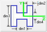
|
dim1 (Start/End) - Specify the web height shown in the diagram for the cross-section at the start and end.
dim2 (Start/End) - Specify the cumulative flange thickness shown in the diagram for the cross-section at the start and end.
dim3 (Start/End) - Specify the height shown in the diagram for the cross-section at the start and end.
dim4 (Start/End) - Specify the web thickness shown in the diagram for the cross-section at the start and end.
|
|
Hat 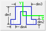
|
dim1 (Start/End) - Specify the section height shown in the diagram for the cross-section at the start and end.
dim2 (Start/End) - Specify the web thickness shown in the diagram for the cross-section at the start and end.
dim3 (Start/End) - Specify the width shown in the diagram for the cross-section at the start and end.
dim4 (Start/End) - Specify the flange extension thickness shown in the diagram for the cross-section at the start and end.
|
|
I 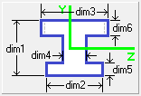
|
dim1 (Start/End) - Specify the section height shown in the diagram for the cross-section at the start and end.
dim2 (Start/End) - Specify the bottom flange width shown in the diagram for the cross-section at the start and end.
dim3 (Start/End) - Specify the top flange width shown in the diagram for the cross-section at the start and end.
dim4 (Start/End) - Specify the web thickness shown in the diagram for the cross-section at the start and end.
dim5 (Start/End) - Specify the bottom flange thickness shown in the diagram for the cross-section at the start and end.
dim6 (Start/End) - Specify the top flange thickness shown in the diagram for the cross-section at the start and end.
|
|
I1 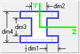
|
dim1 (Start/End) - Specify the cumulative flange extension shown in the diagram for the cross-section at the start and end.
dim2 (Start/End) - Specify the web thickness shown in the diagram for the cross-section at the start and end.
dim3 (Start/End) - Specify the web height shown in the diagram for the cross-section at the start and end.
dim4 (Start/End) - Specify the section height shown in the diagram for the cross-section at the start and end.
|
|
L 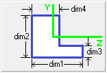
|
dim1 (Start/End) - Specify the section width shown in the diagram for the cross-section at the start and end.
dim2 (Start/End) - Specify the section height shown in the diagram for the cross-section at the start and end.
dim3 (Start/End) - Specify the flange thickness shown in the diagram for the cross-section at the start and end.
dim4 (Start/End) - Specify the web thickness shown in the diagram for the cross-section at the start and end.
|
|
Rod 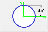
|
dim1 (Start/End) - Specify the section radius shown in the diagram for the cross-section at the start and end.
|
|
T 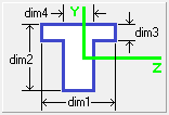
|
dim1 (Start/End) - Specify the flange width shown in the diagram for the cross-section at the start and end.
dim2 (Start/End) - Specify the section height shown in the diagram for the cross-section at the start and end.
dim3 (Start/End) - Specify the flange thickness shown in the diagram for the cross-section at the start and end.
dim4 (Start/End) - Specify the web thickness shown in the diagram for the cross-section at the start and end.
|
|
T1 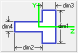
|
dim1 (Start/End) - Specify the flange height shown in the diagram for the cross-section at the start and end.
dim2 (Start/End) - Specify the web height shown in the diagram for the cross-section at the start and end.
dim3 (Start/End) - Specify the flange thickness shown in the diagram for the cross-section at the start and end.
dim4 (Start/End) - Specify the web thickness shown in the diagram for the cross-section at the start and end.
|
|
T2 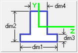
|
dim1 (Start/End) - Specify the flange width shown in the diagram for the cross-section at the start and end.
dim2 (Start/End) - Specify the section height shown in the diagram for the cross-section at the start and end.
dim3 (Start/End) - Specify the flange thickness shown in the diagram for the cross-section at the start and end.
dim4 (Start/End) - Specify the web thickness shown in the diagram for the cross-section at the start and end.
|
|
Tube 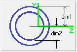
|
dim1 (Start/End) - Specify the outer radius shown in the diagram for the cross-section at the start and end.
dim2 (Start/End) - Specify the inner radius shown in the diagram for the cross-section at the start and end.
|
|
Z 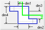
|
dim1 (Start/End) - Specify the flange extension shown in the diagram for the cross-section at the start and end.
dim2 (Start/End) - Specify the web thickness shown in the diagram for the cross-section at the start and end.
dim3 (Start/End) - Specify the web height shown in the diagram for the cross-section at the start and end.
dim4 (Start/End) - Specify the section height shown in the diagram for the cross-section at the start and end.
|
|
The following option is available if Cable is selected:
|
|
Rod 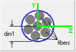
|
dim1 - Specify the radius of the cross-section of the cable.
Number of fibers - Cables are generally made of several strands of wires or fibers. Specify the of fibers for the cable. This number inversely influences the bending stiffness.
|
The following options are available for both the Beam and Cable types:
|
MaterialProperty
|
Select the material property for the body.
|
Damping Factor
|
Specify material damping.
|
Number of segments
|
Specify the discretization per element along the three axes of the beam/cable. These parameters are used for visualization in HyperView. The number of segments also influences the display of stress and deformation contours.
|
Manage Materials
|
Click to display the Material Properties dialog.
|