|
»Click here to display Table of Contents«
|

Belt-Pulley Subsystem |

|

|

|

|
|
Belt-Pulley Subsystem |
|
|
|

|
|
»Click here to display Table of Contents«
|
Belt-Pulley Subsystem |
|
|
|
|
|
Belt-Pulley Subsystem |
|
|
|
|
In a belt-pulley system, a long flexible belt is used to transmit mechanical power by wrapping the belt around rotating pulleys. The power is transmitted due to friction between the belt and pulley surface.
The belt-pulley subsystem in MotionView helps in assembling such a system very quickly with a minimal set of inputs such as pulley center position, radius, and belt properties.
A Belt-Pulley can be added in MotionView using the Belt Pulley Subsystem icon ![]() located on the Subsystems toolbar.
located on the Subsystems toolbar.
MotionView offers two types of belt pulley systems:
| • | Nonlinear Finite Element (NLFE) based – The belt is modeled as a series of connected nonlinear finite element beams. Use this model if you are interested in a high fidelity model that returns accurate belt stresses and strains. Note: these simulations can take a long time. |
| • | Discretized rigid bodies – The belt is modeled as a series of rigid bodies connected by bushings. Use this model if you are interested in the overall motion of the belt pulley system. Note: these simulations are usually faster than similar ones with NLFE belts. |
In both cases, the system is modeled in such a way that the pulley centers lie in the X-Z plane of the reference marker used to model the system.
| Note | An NLFE belt currently can only be modeled such that the Y-axis of belt pulley system Marker reference is parallel to the Global Y. This limitation will be removed in a later release. |
A Belt-Pulley needs the following entities to be present in the model:
A reference marker, such that the X-Z plane of the marker coincides with the plane formed by the pulley, centers when the belt pulley system lies in a plane other than the Global XZ. In the case of an NLFE belt formulation, the XZ plane has to be parallel to the Global XZ plane.
Click on the Belt-Pulley Subsystem toolbar icon ![]() to invoke the Add a Belt-Pulley Subsystem dialog.
to invoke the Add a Belt-Pulley Subsystem dialog.
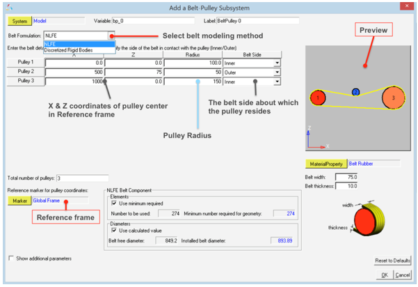
Add a Belt-Pulley System dialog
| 1. | Double click on the System collector (located in the top left corner of the dialog) to select the system in which the Belt-Pulley is to be created. |
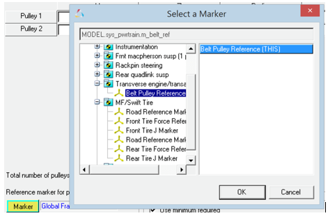
| 2. | Select the Reference marker for pulley coordinates by double clicking on the Marker collector (located in the lower left corner of the dialog), if a reference frame other than Global Frame is to be used. The belt pulley system will be created such that the assembly lies within the X-Z plane of the reference frame. |
| 3. | Select the type of Belt Formulation to represent the belt using the drop-down menu (NLFE or Discretized Rigid Bodies). |
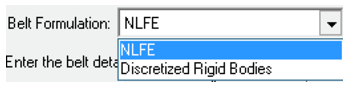
The NLFE formulation creates a non-linear finite element representation the belt using nonlinear beam finite elements.
The Discretized Rigid Bodies formulation represents the belt as a chain of connected rigid bodies.
| 4. | By default, two pulleys are available. To add or delete a pulley, use the right-click option on a row item indicating the pulley number. |
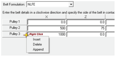
Note Pulleys are numbered sequentially in the clockwise direction.
| 5. | Enter the pulley details as described in the table below: |
Parameters common to both types of formulations |
||
X |
The X coordinate value of the pulley center in Reference marker coordinate frame. |
|
Z |
The Z coordinate value of the pulley center in Reference marker coordinate frame. |
|
Radius |
The radius of the pulley. |
|
Belt Side |
Indicates which side (Inner or Outer) of the belt loop the pulley is positioned. |
|
Belt width |
The width of the belt. |
|
Belt thickness |
The thickness of the belt. |
|
Total number of pulleys |
The total number of pulleys to be created. As the pulley is added/deleted this field will be automatically updated. Changing values in this field changes the number of pulleys. |
|
Parameters specific to NLFE Belt-Pulley |
||
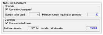
NLFE Belt Components |
|
|
Elements |
||
|
Minimum number required for geometry |
The number of NLFE beam elements required to accurately represent the belt based on the calculated belt profile. |
|
Use minimum required |
Use minimum number of required elements as calculated by the above parameter. Check this option off to use more numbers of elements. |
|
Number to be used |
With the Use minimum required option is off, specify number of NLFE beam elements to be created that is greater than the minimum required. |
Diameters |
||
|
Installed belt diameter |
Effective diameter based on the calculated profile length of the belt in the installed position. |
|
Belt free diameter |
Diameter of the belt in the uninstalled or free position. This number should be smaller than the Installed belt diameter, so that the belt is sufficiently pre-tensioned. The greater the difference between the free diameter and the Installed diameter, the more pretension is induced. |
|
Use Calculated value |
The dialog sets a value for the free diameter by a known amount of offset from the Installed free diameter. Check this off to provide a different value for the belt free diameter. |
Parameters specific to Discretized Rigid Bodies Belt-Pulley |
||
|
||
|
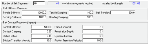
Number of Belt Segments |
The number of body segments the belt needs to be divided into. |
|
Minimum segments required |
The minimum number of belt segments required to accurately represent the belt based on the calculated belt profile. |
|
Installed belt length |
Effective length of belt based on the calculated profile of the belt in the installed position. |
Belt stiffness properties |
||
|
Tensile stiffness |
Stiffness along longitudinal direction of the belt. |
|
Bending stiffness |
Stiffness along bending direction of the belt. |
|
Tensile damping |
Damping along longitudinal direction of the belt. |
|
Bending damping |
Damping along bending direction of the belt. |
|
Belt tension |
The pre-tension in the belt. |
|
Belt Contact Properties (Impact) |
The parameters under this category are the same as that found in Contact panel with Impact method. Refer to the Contacts panel topic to learn more about each of the parameters. |
| a. | As the Pulley X, Z, radii, and the belt side parameters are set, the preview image shows the belt pulley system configuration. The line joining the pulleys tangentially represents the belt. For any incompatible information (for example, overlapping locations of the pulleys, distance between two pulley centers smaller than the summation of their radii) the belt line would not be visible. |
| b. | Cross belt and out of plane pulley configurations are not supported. |
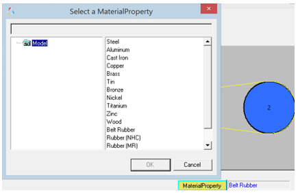
| 6. | A linear elastic Belt Rubber material is available in MotionView and is selected by default. To use a different material, double click on the MaterialProperty collector and select a different material from the list. |
| - | Once all the above information is entered click OK to create the belt pulley system and exit the dialog. |
| Note | The Discretized Rigid body system contains a large set of markers and contact definitions. Creating and working with such a system could be slow in MotionView. |
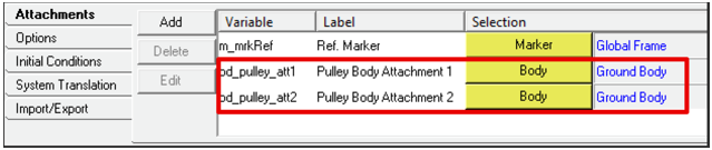
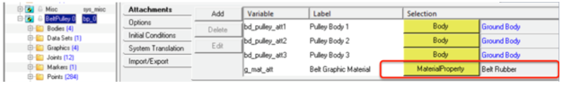
The pulleys, by default, are connected to Ground Body via revolute joints. To change this attachment to a different body, select the Belt-Pulley system in the browser and change the attachments in the Attachments tab as shown below:
Once the belt pulley system is built, the material of the belt can be changed through the material attachment to the Belt Pulley system in the Attachments tab:
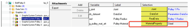
The pulley material can be changed by selecting the graphic system of the pulley and changing the material attachment in the Attachments tab:
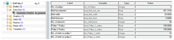
Belt Parameters can be changed through the dataset Parameters DataSet available within the belt pulley system.
The parameters that are active can be changed, while those that cannot be changed are grayed out.
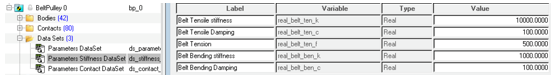
In the case of Discretized rigid bodies Belt, the stiffness parameter and belt tension can be changed using the dataset Parameters Stiffness DataSet:
The Belt-Pulley system that is created has the following architecture:
Bodies |
Rigid pulley bodies and an NLFE belt body consisting of a series of nonlinear beam finite elements are created. |
DataSet |
A dataset where all editable values are stored. After the creation of the belt pulley system, you can change the free diameter and width of the belt through this dataset. |
Points |
The points that define the uninstalled belt profile and the pulley centers. These are hidden by default. |
Graphics |
The graphics for the pulleys. |
Joints |
Revolute joints between the pulley and attaching body. In addition, there are joints that connect the pulley and belt body that help in transmitting motion. |
Markers |
A reference marker to define the uninstalled configuration of the belt (hidden by default). |
Template |
Includes NLFE statements that are currently not supported by MotionView. These include GRIDS at the periphery of the pulley, LINE2 elements that model contact between belt GRID and pulley GRID, and CONN1 elements that restrain the belt with the pulley along normal of the belt pulley plane. |
The organization of the NLFE Belt-Pulley system definition in the model tree view is shown below:
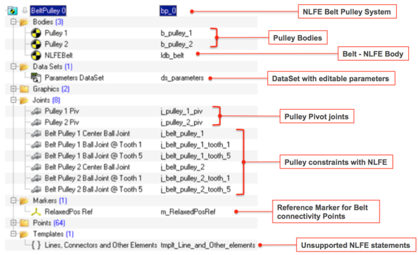
Belt-Pulley NLFE system definition and entities
The Discretized rigid bodies Belt-Pulley has the following architecture:
Bodies |
Rigid pulley bodies and a belt body consisting of a series of connected rigid bodies is created. |
DataSet |
A dataset where all editable values are stored. After the creation of the belt pulley system, you can change the free diameter and width of the belt through this dataset. |
Points |
The points that define the uninstalled belt profile and the pulley centers. These are hidden by default. |
Graphics |
Graphics for the pulleys and belt. |
Joints |
Revolute joints between pulley and attaching body. In addition there are joints that connect the pulley and belt that hold the belt in the system plane. |
Markers |
A reference marker to define the uninstalled configuration of the belt (hidden by default). |
Template |
Includes MotionSolve command statements to hide the graphics used in contact. |
The organization of the Discretized Rigid Bodies Belt-Pulley system definition in the model tree view is shown below:
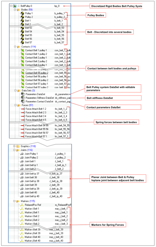
Discretized Rigid Bodies Belt-Pulley system definition and entities