Systems Review Dialog |

|

|

|

|
|
Systems Review Dialog |

|

|

|

|
The Systems Review dialog allows you to review the orientations of various element systems (1D, 2D, or 3D), as well as material and ply systems. Reviewing these systems enables you to assess the integrity of model and understand the results in significance to the system of interest. Element systems can be reviewed to check normal orientations, proper connectivity, or the beam orientations. While most of these checks are performed in the pre-processing stage, this tool acts like a verification aide in post-processing. The system plots can be overlaid with Vector and Tensor plots to confirm that the results and their orientations are accurate. Various display options are available which allow you to customize the appearance of the system plot.
To access this dialog, click on the System button ![]() on the Results toolbar, or from the Result menu select Plot > System.
on the Results toolbar, or from the Result menu select Plot > System.

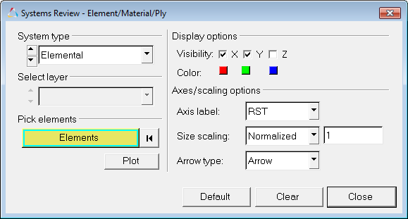
Systems Review - Element/Material/Ply dialog
Note - For reviewing 1D Elemental, Ply, and Material systems, the Advanced Result Math template must be selected in the Load Model panel when initially loading the model and result file. In addition, a solver input deck is also required as the model file.
The various options available in the dialog allow you to control the display and visualization of the systems in the graphics area:
System type |
The current system type selected for view is displayed, however you can use the drop-down menu to make another selection from the list. You can also use the arrow up/down buttons |
|
Elemental |
Select to review the orientations of the following element systems:
|
|||||||||||||
|
Material |
Select to review the orientations of various material systems.
|
|||||||||||||
|
Ply |
Select to review the orientations of various ply systems.
|
Select layer |
The current layer selected for view is displayed; however you can use the drop-down menu to make another selection from the list. You can also use the arrow up/down buttons Note - this option is only applicable for Ply systems (it will be disabled/grayed out for all Elemental and Material systems). |
Pick entities |
Before plotting and reviewing a system, you may pick one or more elements or components from the model. You can do this by picking entities directly from the screen, using the quick window selection, or by clicking the Elements (or Components) input collector |
Plot |
Click to apply and plot the various options for the selected system. |
Display options |
The following options allow you to change how the vectors are displayed and will automatically be applied to the model: |
|
Visibility |
You can create a vector plot using the X, Y, or Z axis. |
|
|
X, Y, Z |
Quickly turn on/off each axis by activating/deactivating each check box. By default only the X and Y axis are checked for display. |
|
Color |
Allows you to select the vector color for the X, Y, or Z axis. |
|
|
X, Y, Z |
To change the color of an axis, click the color box to display the color palette and then select a different color. |
Axes/scaling options |
The following options allow you to change the axis label, scaling, and arrow type used for the displayed vectors. |
|
Axis Label |
Use the drop-down menu to select the axis label: |
|
|
XYZ |
Displays the axis for each vector as X, Y, and Z. |
|
|
RST |
Displays the axis for each vector as R, S, and T. |
|
|
UVW |
Displays the axis for each vector as U, V, and W. |
|
|
123 |
Displays the axis for each vector as numerical values 1, 2, and 3. |
|
|
None |
Displays the vector head as a straight line. |
|
Size scaling |
Use the drop-down menu to select the vector size scaling method: |
|
|
Normalized |
Automatically scales the vector length (the average vector length will be approximately 2% of the model size). This is set as the default scale mode. |
|
|
Uniform |
All vectors are displayed in a uniform size. You can increase or decrease the size using the Scale value text box (located to the right of the drop-down menu). |
|
Arrow type |
Use the drop-down menu to display the vector head as an arrow or a straight line: |
|
|
Arrow |
Displays the vector head as an arrow. |
|
|
None |
Displays the vector head as a straight line. |
Clear |
Click to clear the current plot for the selected system in the graphics area. Note - The dialog will remain open. |
Close |
Click to close/exit the dialog. All current plots will remain displayed in the graphics area (until they are cleared using the Clear button). |
See also