Field
|
Contents
|
SI Unit Example
|
mat_ID
|
Material identifier
(Integer, maximum 10 digits)
|
|
unit_ID
|
Optional unit identifier
(Integer, maximum 10 digits)
|
|
mat_title
|
Material title
(Character, maximum 100 characters)
|
|

|
Initial density
(Real)
|

|
E11
|
Young‘s modulus in direction 1
(Real)
|

|
E22
|
Young’s modulus in direction 2
(Real)
|

|

|
Poisson’s ratio
(Real)
|
|
Iform
|
Formulation flag (Comment 1)
(Integer)
= 1: CRASURV formulation
|
|
E33
|
Young’s modulus in direction 33 (Comment 4)
(Real)
|

|
G12
|
Shear modulus in direction 12
(Real)
|

|
G23
|
Shear modulus in direction 23
(Real)
|

|
G31
|
Shear modulus in direction 31
(Real)
|

|
 f1 f1
|
Maximum tensile strain for element deletion in material direction 1
Default = 1.2 x 1030 (Real)
|
|
f2
|
Maximum tensile strain for element deletion in material direction 2
Default = 1.2 x 1030 (Real)
|
|
t1
|
Tensile failure strain in the material direction 1 at which stress starts to reduce (Comment 6)
Default = 1.0 x 1030 (Real)
|
|
m1
|
Maximum tensile strain in material direction 1 at which the stress in the element is set to a value dependent on dmax (Comment 6)
Default = 1.1 x 1030 (Real)
|
|
t2
|
Tensile failure strain in the material direction 2 at which stress starts to reduce
Default = 1.0 x 1030 (Real)
|
|
m2
|
Maximum tensile strain in material direction 2 at which the stress in the element is set to a value dependent on dmax.
Default = 1.1 x 1030 (Real)
|
|
dmax
|
Maximum damage factor (dmax < 1) (Comment 6)
Default = 0.999 (Real)
|
|

|
Maximum plastic work per unit shell volume
Default = 1030 (Real)
|

|

|
Reference plastic work per unit shell volume (Comment 17)
Default = 1.0 (in local unit system) (Real)
|
|
Ioff
|
Flag that controls shell and thick shell element deletion depending on failure modes in the element layers.
(Integer)
= 0: shell is deleted if  for one element : shell is deleted if for one element : shell is deleted if  for one element layer. for one element layer.
= 1: shell is deleted if  for all element layers. for all element layers.
= 2: shell is deleted if for each element layer,
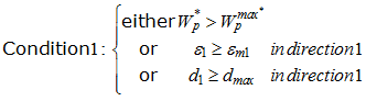
= 3: shell is deleted if for each element layer,
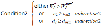
= 4: shell is deleted if for each element layer, condition 1 and condition 2 are satisfied.
= 5: shell is deleted if all element layers, condition 1 or condition 2 is satisfied.
= 6: shell is deleted if for each element layer condition 1 or condition 2 is satisfied.
|
|
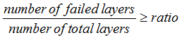
ratio
|
Ratio parameter which controls the deletion of shell elements based on the number of failed layers (Comment 9)
Default = 1.0 (Real)
< 0.0: the element will be deleted if all layers but one failed (that is, the number of layers that did not fail is equation to 1).
> 0.0: the element will be deleted if
|
|
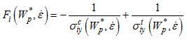
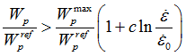
c
|
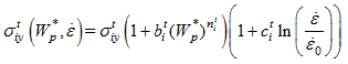
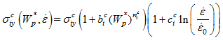
Global strain rate coefficient for plastic work criteria
(Real)
= 0.0: there is no strain rate dependency
|
|

|
Reference strain rate
If  , no strain rate effect , no strain rate effect
(Real)
|

|

|
Reduction factor for F12 coefficient calculation in Tsai-Wu criterion
Default set to 1.0 (Real)
|
|
ICCglobal
|
Global strain rate effect flag (Comment 11)
(Integer)
= 0: default set to 1
= 1: strain rate effect on  , ,  , ,  , ,  , ,  is taken into account, but there is no strain rate effect on is taken into account, but there is no strain rate effect on 
= 2: there is no strain rate effect on  , ,  , ,  , ,  , ,  and and 
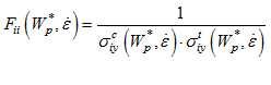
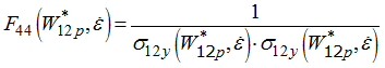
= 3: there is strain rate effect on  , ,  , ,  , ,  , ,  and and 
= 4: strain rate effect on  is taken into account, but there is no strain rate effect on is taken into account, but there is no strain rate effect on  , ,  , ,  , ,  , and , and 
|
|

|
Yield stress in tension in direction 1
Default = 0.0 (Real)
|

|

|
Plastic hardening parameter in tension in direction 1
Default = 0.0 (Real)
|
|

|
Plastic hardening exponent in tension in direction 1
Default = 1.0 (Real)
|
|

|
Maximum stress in tension in direction 1
Default = 1030 (Real)
|

|

|
Strain rate coefficient in tension in direction 1
Default = c (Real)
= 0: no strain rate dependency
|
|

|
Initial softening strain in tension in the material direction 1
Default = 1.0 x 1030 (Real)
|
|

|
Maximum softening strain in tension in the material direction 1
Default = 1.2 *  (Real) (Real)
|
|

|
Residual stress in tension in direction 1
Default = 10-3 *  (Real) (Real)
|

|

|
Maximum plastic work per unit shell volume in tension in direction 1
Default = 1030 (Real)
|
|

|
Yield stress in tension in direction 2
Default = 0.0 (Real)
|

|

|
Plastic hardening parameter in tension in direction 2
Default = 0.0 (Real)
|
|

|
Plastic hardening exponent in tension in direction 2
Default = 1.0 (Real)
|
|

|
Maximum stress in tension in direction 2
Default = 1030 (Real)
|

|

|
Strain rate coefficient in tension in direction 2
Default = c (Real)
= 0: no strain rate dependency
|
|

|
Initial softening strain in tension in the material direction 2
Default = 1.0 x 1030 (Real)
|
|

|
Maximum softening strain in tension in direction 2
Default = 1.2 *  (Real) (Real)
|
|

|
Residual stress in tension in direction 2
Default = 10-3 *  (Real) (Real)
|

|

|
Maximum plastic work per unit shell volume in tension in direction 2
Default = 1030 (Real)
|
|

|
Yield stress in compression in direction 1
Default = 0.0 (Real)
|

|

|
Plastic hardening parameter in compression in direction 1
Default =  (Real) (Real)
|
|

|
Plastic hardening exponent in compression in direction 1
Default =  (Real) (Real)
|
|

|
Maximum stress in compression in direction 1
Default = 1030 (Real)
|

|

|
Strain rate coefficient in compression in direction 1
Default = c (Real)
= 0: no strain rate dependency
|
|

|
Initial softening strain in compression in the material direction 1
Default = 1.0 x 1030 (Real)
|
|

|
Maximum softening strain in compression in the material direction 1
Default = 1.2 *  (Real) (Real)
|
|

|
Residual stress in compression in direction 1
Default = 10-3 *  (Real) (Real)
|

|

|
Maximum plastic work per unit shell volume in compression in direction 1
Default = 1030 (Real)
|
|

|
Yield stress in compression in direction 2
Default =0.0 (Real)
|

|

|
Plastic hardening parameter in compression in direction 2
Default =  (Real) (Real)
|
|

|
Plastic hardening exponent in compression in direction 2
Default =  (Real) (Real)
|
|

|
Maximum stress in compression in direction 2
Default = 1030 (Real)
|

|

|
Strain rate coefficient in compression in direction 2
Default = c (Real)
= 0: no strain rate dependency
|
|

|
Initial softening strain in compression in the material direction 2
Default = 1.0 x 1030 (Real)
|
|

|
Maximum softening strain in compression in the material direction 2
Default = 1.2 *  (Real) (Real)
|
|

|
Residual stress in compression in direction 2
Default = 10-3 *  (Real) (Real)
|

|

|
Maximum plastic work per unit shell volume in compression in direction 2
Default = 1030 (Real)
|
|

|
Yield stress in direction 12 (in 45 degree of fiber direction)
Default = 0.0 (Real)
|

|

|
Plastic hardening parameter in direction 12
Default =  (Real) (Real)
|
|

|
Plastic hardening exponent in direction 12
Default =  (Real) (Real)
|
|

|
Maximum stress in direction 12
Default = 1030 (Real)
|

|

|
Strain rate coefficient in direction 12
Default = c (Real)
= 0: no strain rate dependency
|
|

|
Initial softening strain in the material direction 12
Default = 1.0 x 1030 (Real)
|
|

|
Maximum softening strain in the material direction 12
Default = 1.2 *  (Real) (Real)
|
|

|
Residual stress in direction 12
Default = 10-3 *  (Real) (Real)
|

|

|
Maximum plastic work per unit shell volume in direction 12
Default = 1030 (Real)
|
|

|
Out of plane shear strain when delamination begins (Comment 12)
Default = 1030 (Real)
|
|

|
Out of plane shear strain when delamination ends and the element is deleted (Comment 12)
Default = 1.1 * 1030 (Real)
|
|
d3max
|
Maximum delamination damage factor (d3max < 1) (Comment 14)
Default = 1.0 (Real)
|
|
Fsmooth
|
Strain rate smoothing flag
(Integer)
= 0: strain rate smoothing is inactive (default)
= 1: strain rate smoothing is active
|
|
Fcut
|
Cutoff frequency for strain rate smoothing
Default = 1030 (Real)
|

|


 in directions,
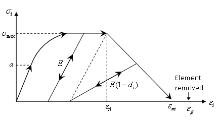
 and
and 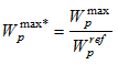
 becomes greater than the value of