Field
|
Contents
|
SI Unit Example
|
prop_ID
|
Property identifier
(Integer, maximum 10 digits)
|
|
unit_ID
|
Optional unit identifier
(Integer, maximum 10 digits)
|
|
prop_title
|
Property title
(Character, maximum 100 characters)
|
|
Isolid
|
Solid elements formulation flag
(Integer)
= 14: HA8 locking-free 8-node thick shell, co-rotational, full integration, variable number of Gauss points in all directions.
= 15: HSEPH/PA6 thick shell (8-node and 6-node respectively), co-rotational, under integrated (1-point in-plan quadrature) with physical stabilization, variable number of integration points in thickness direction.
|
|
Ismstr
|
Small strain formulation flag
(Integer)
= 0: default, set to value defined in /DEF_SOLID
= 1: small strain from time =0
= 2: full geometric nonlinearities with possible small strain formulation in RADIOSS Engine (/DT/BRICK/CST)
= 3: simplified small strain formulation from time =0 (non-objective formulation)
= 4: full geometric nonlinearities (/DT/BRICK/CST has no effect)
|
|
Icstr
|
Constant stress formulation flag (Isolid = 14 only)
(Integer)
= 001: reduced stress integration in t direction
= 010: reduced stress integration in s direction
= 100: reduced stress integration in r direction
|
|
Inpts
|
Number of integration points (Comment 2)
(Integer)
= j: 1 < j < 200 for Isolid =15
= ijk: 2 < i,j,k < 9 for Isolid =14
where:
i = number of integration points in r direction
j = number of integration points in s direction
k = number of integration points in t direction
|
|
Iint
|
Number of layers when 9 < number of layers < 200 (Isolid = 14 only) (Comment 3)
(Integer)
|
|
dn
|
Numerical damping for stabilization (Isolid = 15 only)
Default = 0.1 (Real)
|
|
qa
|
Quadratic bulk viscosity
Default = 1.10 (Real)
Default = 0.0 for /MAT/LAW70
|

|
qb
|
Linear bulk viscosity
Default = 0.05 (Real)
Default = 0.0 for /MAT/LAW70
|
|
Ashear
|
Shear factor
Default = 1.0 (Real)
|
|
VX
|
X component for reference vector
Default = 1.0 (Real)
|
|
VY
|
Y component for reference vector
Default = 0.0 (Real)
|
|
VZ
|
Z component for reference vector
Default = 0.0 (Real)
|
|
skew_ID
|
Skew identifier
If the local skew has been defined, its X-axis replaces the reference vector (VX, Vy, and VZ will be ignored).
(Integer)
|
|
Iorth
|
Orthotropic system formulation flag for reference vector
Default = 0 (Integer)
= 0: the first axis of orthotropy is maintained at constant angle with respect to the orthonormal co-rotational element coordinate system.
= 1: the first orthotropy direction is constant with respect to a non-orthonormal isoparametric coordinates.
|
|
Ipos
|
Layer positioning flag for reference vector
Default = 0 (Integer)
= 0: layer positions are automatically calculated with regard to layer thicknesses partition. The coherence of global thickness with the sum of layer thicknesses is automatically checked.
= 1: all layer positions in the element thickness are user-defined. Multiple layers may have the same special position.
|
|

|
Minimum time step
Default = 106 (Real)
|

|
 1 1
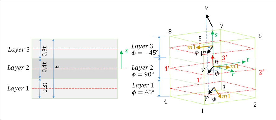
|
Angle for layer i
(Real)
|

|
ti/t
|
Relative thickness of layer i.
where,
ti is the thickness of i_th layer, and
t is the total thickness
(Real)
|
|
Zi
|
Z position (normalized by the thickness) of layer i
(-0.5 < Zi < 0.5)
Default = 0.0 (Real)
|
|
mat_IDi
|
Material identifier for layer i
(Integer)
|
|