|
»Click here to display Table of Contents«
|

PCOMPG |

|

|

|

|
|
PCOMPG |
|
|

|

|
|
»Click here to display Table of Contents«
|
PCOMPG |
|
|
|
|
|
PCOMPG |
|
|
|
|
Bulk Data Entry
PCOMPG – Composite Laminate Property
Description
Defines the structure and properties of a composite laminate material, allowing for global ply identification.
Format
(1) |
(2) |
(3) |
(4) |
(5) |
(6) |
(7) |
(8) |
(9) |
(10) |
PCOMPG |
PID |
Z0 |
NSM |
SB |
FT |
TREF |
GE |
LAM |
|
|
GPLYID1 |
MID1 |
T1 |
THETA1 |
SOUT1 |
|
|
|
|
|
GPLYID2 |
MID2 |
T2 |
THETA2 |
SOUT2 |
|
|
|
|
|
… |
… |
… |
… |
… |
|
|
|
|
|
DS |
|
|
|
|
|
|
|
|
|
Field |
Contents |
PID |
Unique composite property identification number. No default (Integer > 0) |
Z0 |
Real number or character input (Top/Bottom) Real Number - It represents the distance from the shell element reference plane to the bottom surface of the shell (Default = -0.5 * Thick, Thick being the composite total thickness (Real or blank)). Character Input - See comment 18. |
NSM |
Nonstructural mass per unit area. No default (Real) |
SB |
Allowable inter-laminar shear stress (shear stress in the bonding material). Disregarded if blank or 0.0. No default (Real > 0.0) |
FT |
Failure theory code. If blank, no failure calculations are performed. The following failure theory codes are supported: HILL for Hill theory HOFF for Hoffman theory TSAI for Tsai-Wu theory STRN for Maximum Strain theory HASH for Hashin criteria PUCK for Puck failure criteria See comments 14 through 16, and 19. Default = no failure calculations are performed (HILL, HOFF, TSAI, STRN, HASH or PUCK) |
TREF |
Reference (stress free) temperature. See comment 1. Default = 0.0 (Real) |
GE |
Damping coefficient. See comments 10 and 11. Default = 0.0 (Real) |
LAM |
Laminate option. If blank, all plies must be specified and all stiffness terms are developed. The following options are supported: MEM: All plies must be specified, but only membrane terms MID1 are developed. Z0 is ignored (assumed to be: -0.5 * Thick). BEND: All plies must be specified, but only bending terms MID2 are developed. Z0 is ignored (assumed to be: -0.5 * Thick). SMEAR: All plies must be specified, stacking sequence is ignored, and MID1 is set equal to MID2 on the derived equivalent PSHELL, while MID3, MID4, TS/T, and 12I/T**3 are set to blank. Z0 is ignored (assumed to be: -0.5 * Thick). SMEARZ0: All plies must be specified, stacking sequence is ignored. While the laminate is still considered to be made of homogenized (smeared) material, the effect of offset Z0 is taken into account. Hence, if Z0 ≠ -0.5 * Thick, the equivalent PSHELL will include MID1, MID2 and MID4. MID3 is still set to blank, that is no transverse shear deformation is considered. SMCORE: All plies must be specified. The last ply specifies core properties and the previous plies specify face sheet properties. The face sheet properties are calculated without regard for stacking sequence; half of the total face sheet thickness is then placed on top of the core, and half is placed on the bottom, to produce a symmetric laminate. Stiffness of the core is ignored while its density is included in inertia calculations. Z0 is ignored (assumed to be: -0.5 * Thick). SYMEM: Only plies on the bottom half of the composite lay-up needs to be specified. These plies are automatically symmetrically reflected to the top half of the composite and given consecutive numbers from bottom to top. Only membrane terms are developed for the full laminate. Z0 is ignored (assumed to be: -0.5 * Thick). SYBEND: Only plies on the bottom half of the composite lay-up needs to be specified. These plies are automatically symmetrically reflected to the top half of the composite and given consecutive numbers from bottom to top. Only bending terms are developed for the full laminate. Z0 is ignored (assumed to be: -0.5 * Thick). SYSMEAR: Only plies on the bottom half of the composite lay-up needs to be specified. These plies are automatically symmetrically reflected to the top half of the composite and given consecutive numbers from bottom to top. Stacking sequence is ignored, and MID1 is set equal to MID2 on the derived equivalent PSHELL, while MID3, MID4, TS/T and 12I/T**3 are set to blank. Z0 is ignored (assumed to be: -0.5 * Thick). Default = blank, that is all plies must be specified (SYM, MEM, BEND, SMEAR, SMCORE, SYMEM, SYBEND or SYSMEAR) |
GPLYID# |
Global Ply identification number. See comment 12. No default (Integer > 0) |
MID# |
Material IDs of individual plies. The plies are identified by consecutively numbering them from 1 at the bottom layer. The MIDs must refer to MAT1, MAT2, MAT4, MAT5, or MAT8 bulk data entries. If MID# is not specified, default is the last defined MID#. Default = last defined MID# (Integer > 0 or blank, except that MID1 must be specified) |
T# |
Thicknesses of individual plies. If T# is not specified, default is the last defined T#. Default = last defined T# (Real > 0.0 or blank, except that T1 must be specified) |
THETA# |
Orientation angle, in degrees, of the longitudinal direction of each ply relative to the x-axis of the material coordinate system associated with a given element. If no material coordinate system is specified for the element, the angle is measured relative to side 1-2 of this element. Default = 0.0 (Real or blank) |
SOUT# |
Stress and failure index output request for individual plies. See comments 2 and 3. Default = NO (YES or NO) |
DS |
Design switch. If non-zero (1.0), the elements associated with this PCOMP data are included in the topology design volume or space. Default = blank (Real = 1.0 or blank) |
| 1. | TREF specified on the PCOMPG entry overrides reference temperatures given for individual ply materials. If TREF is not specified (blank) on the PCOMPG card, then all the ply materials must have the same reference temperature. |
| 2. | For SOUTi to take effect, CSTRESS must be requested in the I/O options section of the input deck. Individual ply results will be available in addition to shell stresses and strains based on the homogenized composite properties. |
| 3. | An additional piece of information available with ply results is "failure index for the element", which is the maximum of failure indices for individual plies in this element. Only the plies with SOUTi set to YES are considered in the evaluation of this maximum. |
| 4. | If all plies specify zero transverse shear coefficients (G1Z, G2Z on MAT8 card, isotropic G for MAT1, not available for MAT2), the in-plane shear modulus will be used to determine transverse shear stiffness of the composite. |
|
| 5. | The signs given to stress limits for compression and tension (ST, SC, for MAT1; Xt, Xc, and so on for MAT8) are of no relevance. Absolute values are taken and used in the appropriate context to calculate failure indices. |
| 6. | For composites with offset (Z0 ≠ 0.5 * Thickness), correct values of shell stresses for the bottom and top surfaces of the shell are produced. |
|
| 7. | For composites with offset (Z0 ≠ 0.5 * Thickness) the buckling results will not be correct. This is because the membrane-bending coupling resulting from composite offset is not included in the differential stiffness matrix. Therefore, the preferred method of incorporating offset in buckling analysis is the element offset ZOFFS. |
| 8. | Element GRID thicknesses cannot be defined for elements that reference PCOMPG data. |
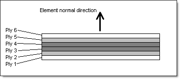
| 9. | Plies are listed from the bottom surface upwards, in respect to the element’s normal direction. The image below shows the stacking sequence for a non-symmetrical laminate. |
| 10. | GE given on the PCOMP entry will be used for the element, and the values supplied on material entries for individual plies are ignored. You are responsible for supplying the equivalent damping value on the PCOMPG entry. |
| 11. | To obtain the damping coefficient GE, multiply the critical damping ratio C/C0 by 2.0. |
| 12. | The global ply identification number must be unique with respect to other plies in the entry. |
| 13. | For convenience, element output for the SMEAR and SMCORE options includes both homogenized shell stresses and individual ply stresses. However, because stacking sequence is ignored in these options, individual ply stresses will only be valid in cases of pure membrane deformation. |
| 14. | Note that Hill’s failure theory does not differentiate between compressive and tensile strength. While different values of respective strength limits are accepted, it is still recommended that Xt is set to be equal to Xc and Yt is set to be equal to Yc when this criteria is used. Xt and Xc are allowable tensile and compressive stresses in the principle x direction of the material. Yt and Yc are allowable tensile and compressive stresses in the principle y direction of the material. |
| 15. | Failure index calculation according to Maximum Strain Theory is based on mechanical component of strain only, not on total strain. This is because only the mechanical strain contributes to actual damage of the respective ply (pure thermal expansion produces no damaging effects). |
| 16. | According to the formula, some failure criteria (for example, Tsai-Wu and Hoffman) would produce a negative ply failure, depending on the problem. |
| 17. | If ‘PARAM, SRCOMPS, YES’ is added to the input file, strength ratios with respect to designated failure theory are output for composite elements that have failure indices requested. |
| 18. | The following two formats are permissible for the Z0 field: |
Real Number:
It represents the distance from the shell element reference plane to the bottom surface of the shell (Default = -0.5 * Thick, Thick being the composite total thickness (Real or blank)).
Surface:
Top:
The shell reference plane, the plane defined by the grid points, and the top surface of the shell are coplanar.
This makes the effective "Real" Z0 value equal to the composite total thickness (-1.0 * Thick). See Figure 1.
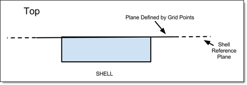
Figure 1: Top option for Z0
Bottom:
The shell reference plane, the plane defined by the grid points, and the bottom surface of the shell are coplanar.
This makes the effective "Real" Z0 value equal to 0. See Figure 2.
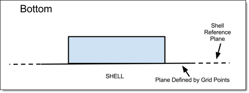
Figure 2: Bottom option for Z0
Automatic offset control is available in composite free-size and sizing optimization where the specified offset values are automatically updated based on thickness changes.
| 19. | The material parameters, Xt, Xc, Yt, Yc, and S on the MAT8 Bulk Data Entry should be specified for failure criteria calculation. |
| 20. | This card is represented as a property in HyperMesh. |
See Also: