PLOAD1 |

|

|

|

|
|
PLOAD1 |

|

|

|

|
Bulk Data Entry
PLOAD1 – Applied Load on CBAR or CBEAM Elements
Description
Defines concentrated, uniformly distributed, or linearly distributed applied loads to the CBAR or CBEAM elements at user-chosen points along the axis. It can also be used to define the EXCITEID field (Amplitude “A”) of dynamic loads in RLOAD1, RLOAD2, TLOAD1 and TLOAD2 bulk data entries.
Format
(1) |
(2) |
(3) |
(4) |
(5) |
(6) |
(7) |
(8) |
(9) |
(10) |
PLOAD1 |
SID |
EID |
TYPE |
SCALE |
X1 |
P1 |
X2 |
P2 |
|
|
Field |
Contents |
SID |
Load set identification number. In the static solution sequences, the load set ID (SID) is selected by the LOAD command in the Subcase Information section. No default (Integer > 0) |
EID |
CBAR or CBEAM element identification number. Must be unique. No default (Integer > 0) |
TYPE |
Load type. "FX", "FY" or "FZ": Force in the x, y, or z direction of the basic coordinate system. "MX", "MY" or "MZ": Moment in the x, y, or z direction of the basic coordinate system. "FXE", "FYE" or "FZE": Force in the x, y, or z direction of the element’s coordinate system. "MXE", "MYE" or "MZE": Moment in the x, y, or z direction of the element’s coordinate system. No default |
SCALE |
Determines scale factor for X1, X2. See comments 2 through 5. No default (LE, FR, LEPR or FRPR) |
X1, X2 |
Distances along the CBAR or CBEAM element axis from end A. If X2 ≠ X1, a linearly varying distributed load will be applied to the element between positions X1 and X2, having an intensity per unit length of bar equal to P1 at X1 and equal to P2 at X2. If X2 is blank or equal to X1, a concentrated load of value P1 will be applied at position X1. For X1: No default For X2: Default = blank (Real, 0 < X1 < X2) |
P1, P2 |
Load factors at positions X1, X2. Default = blank (Real or blank) |
| 1. | If P1 = P2 and X2 ≠ X1, a uniform distributed load of intensity per unit length equal to P1 will be applied between positions X1 and X2, except as noted in comments 8 and 9. |
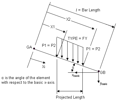
| 2. | If SCALE = LE (length), the xi values are actual distances along the element axis, and, if X1 ≠ X2, the Pi are load intensities per unit length of the element. |
| 3. | If SCALE = FR (fractional), the xi values are ratios of the distance along the axis to the total length, and (if X2 ≠ X1) Pi are load intensities per unit length of the element. |
| 4. | If SCALE = LEPR (length projected), the xi values are actual distances along the element axis, and (if X2 ≠ X1) the distributed load is input in terms of the projected length of the element. |

PLOAD1 Convention on Beam or Bar Elements
If SCALE = LE, the total load applied to the bar is P1 (X2 – X1) in the y-basic direction.
If SCALE = LEPR, the total load applied to the bar is P1 (X2 – X1) cosα in the y-basic direction.
| 5. | If SCALE = FRPR (fractional projected), the Xi values are ratios of the actual distance to the length of the bar (CBAR entry), and if X1 ≠ X2, then the distributed load is specified in terms of the projected length of the bar. |
| 6. | Loads on CBEAM elements defined with PLOAD1 entries are applied along the line of the shear centers. |
| 7. | If the element coordinate system direction (for example, TYPE = FYE) option is selected, then the projection (SCALE=FRPR or LEPR) option is ignored and the result is the same as the SCALE=FR (or LE) option. |
| 8. | This card is represented as a pressure load in HyperMesh. |
See Also: