The Connectivity tab on the Fields panel allows you to define the bodies and orientation used by the compliant connection.
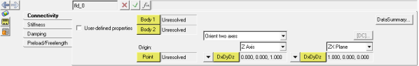
Fields panel - Connectivity tab
Use:
|
To:
|
User- defined properties
|
Activate the check box to define non-linear stiffness and damping properties. After you select User-defined properties, select the User-Defined tab and select a force from the drop-down menu.
|
Body 1
|
The first body used by the field.
|
Body 2
|
The second body used by the field.
|
Point
|
The location of the field.
|
Orient two axes
Orient one axis
Orient by angles
|
Select the method of orientation.
|
X|Y|Z Axis
|
Select the orientation information for the axis.
|
Point 1
Vector 1
DxDyDz
|
Point aligns the axis to a point.
Vector aligns the axis along a vector.
DxDyDz aligns the axis along explicit vector components.
|
Point 2
Vector 2
DxDyDz
|
Point aligns the orientation of the plane using a point.
Vector aligns the orientation of the plane using a vector.
DxDyDz aligns the orientation of the plane using explicit components.
|
XY/XZ/YX/YZ/ZX/ZY
|
Specifies the plane to be oriented.
|
Click DataSummary,  , to view the Data Summary table for fields. , to view the Data Summary table for fields.
|
[DC] allows you to view the direction cosines’ matrix for a coordinate system.
|
| Note | In MotionView, most entities that require orientation, such as bodies, joints, and bushings, have orientation rules directly linked to them; therefore, they do not require markers. |


