
Define CLOAD-Force/Moment on: Node Sets |

|

|

|

|
|
Define CLOAD-Force/Moment on: Node Sets |
|
|
|

|
Define CLOAD-Force/Moment on: Node Sets |
|
|
|
|
|
Define CLOAD-Force/Moment on: Node Sets |
|
|
|
|
The Define CLOAD-Force/Moment on: Node sets option defines CLOAD on node sets. The node set names are used in the *CLOAD data lines instead of the individual nodes. Unlike Abaqus surfaces in Engineering Solutions, you can combine node sets with individual node IDs in the same *CLOAD card.
|
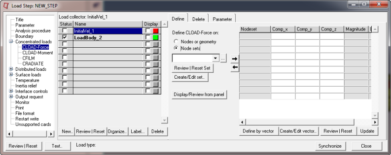
This Define tab for Define CLOAD-Force/Moment on: Node sets includes a Node sets menu containing a list of existing node sets. A data line input table also appears on the Define tab. The table contains the following columns:
Nodeset |
The name of the node sets. Node sets are added or removed using |
Comp_x |
The component in x direction. The x-direction indicates dof 1 for force and dof 4 for moment. |
Comp_y |
The component in y direction. The y-direction indicates dof 2 for force and dof 5 for moment. |
Comp_z |
The component in z direction. The x-direction indicates dof 3 for force and dof 6 for moment. |
Magnitude |
The magnitude. This column is non-editable. The magnitude is calculated based on the Comp_x, Comp_y, and Comp_z defined for each node set when you click Update. |
Load Id |
The ID of the load collector. |
For tips on entering information and navigating in the Define tab, see Step Manager Tab Environment.
The Define tab for Define CLOAD-Force/Moment on: Node sets contains the following buttons:
Review Set |
Reviews the selected node sets by highlighting them in the Engineering Solutions graphics. Right-click Review to clear the review selections. |
Create/Edit Set.. |
Opens the Entity Sets panel. When you finish creating/editing the set, click return. Step Manager is updated with the new set appearing in the node set list. |
Display/Review from panel |
Opens the appropriate panel. Use the review button to expand the loads and constraints on the sets for visualization purposes. |
|
Add the selected node set from the drop-down menu to the data line table on the right. |
|
Delete the selected node set from the data line table. |
Define by vector |
Opens the Vector Selector panel. Pick a vector and click proceed. This vector is used to define the Comp_x, Comp_y, Comp_z, and Magnitude of the CLOAD for the selected node set. |
Create/Edit vector.. |
Opens the Vectors panel. When you finish creating/editing the vector, click return. |
Review |
Creates special review forces or moments in Engineering Solutions graphics for the selected node set. These review forces or moments take into consideration the *TRANSFORM cards that may be associated with nodes in the node set. Right-click Review to clear the special review loads and highlighting. |
Update |
Updates the database with the data lines defined in the table. By default, Engineering Solutions does not display loads defined with sets. |