The Streamlines panel allows you to generate streamlines using any available nodal or elemental vector field (typically a velocity field). In addition, streamlines can also be animated with particles traveling along the streamlines (see below for a description of the various contour and animation options). Velocity fields are directly written to H3D files by many solvers such as: Radioss, HyperXtrude, Moldflow, etc. Velocity fields and other scalar and vector data fields are also saved in EnSight format by most CFD solvers (see Saving EnSight files with Fluent below for additional information).
HyperView has a direct reader of EnSight files, thus allowing post-processing of typical CFD results from a large class of industry practices. The EnSight reader has been enhanced to support particle data (for example, modeling of dust particles in a flow) existent in a data set which can be animated; as well as transient data, including mesh deformation (for example, sliding mesh and ALE). The EnSight file type (*.encas, *.case) is available in the Files of type drop-down menu, located in the Load Model File or Load Results File selection dialog. In addition, Ensight files produced by SC/Tetra and other CFD solvers (for example, AcuSolve, Fluent, etc.) can also be loaded into HyperView by selecting the Auto option from the drop-down menu located in the Reader Options dialog. A separate SC/Tetra Ensight files option is also available for loading SC/Tetra files only (see the CFD Ensight Reader topic for additional information).
To access the Streamlines panel, click on the Streamlines button  on the Results toolbar, or select Create > Streamlines from the Results menu.

Streamlines panel
| Note | The Streamlines and Tracers tab will only be displayed if there are items in the Rakes list. |
Rakes List
|
On the left-most side of the panel is the Rakes list. The Streamlines status is also shown in this listing. When streamlines have been created from a rake, the Streamlines status changes from N/A to Available.
After streamlines have been created, deactivating the check box next to the rake will hide the streamlines group in the graphics area. The same Show/Hide functionality can also be accessed by right clicking on any rake item (see below for additional information on Show/Hide).
To select multiple rakes from the Rakes list, press the SHIFT or CTRL key on the keyboard + the left mouse button.
You can sort the items in the Rakes list by clicking on the Rakes or Streamlines headings.
|
Add
|
Adds a new rake to the list. The newly added rake is automatically labeled, and is added to the bottom of the list. To change the name of a rake, right-click on the current name, enter a new name into the Rename dialog, and click OK.
|
Delete
|
Deletes the selected Rake/Streamline pair(s) from the list.
|
You can access the following options by right-clicking anywhere within the Rakes list:
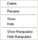
Delete
|
Deletes the selected Rake/Streamline pair(s) from the list.
|
Rename
|
Displays the Rename dialog, which allows you to rename the selected Rake.
|
Show
|
Displays the selected Rake/Streamline pair(s) in the graphics area and activates the corresponding check box(es).
|
Hide
|
Hides the selected Rake/Streamline pair(s) in the graphics area and deactivates the corresponding check box(es).
|
Show Manipulator
|
Displays the graphical manipulator in the graphics area for the currently selected rake/streamline. The Streamlines graphical manipulators allow you to modify the location and shape of the rake interactively by scaling, translating, or rotating the line, plane, or area using a manipulator specific to the rake type (Line, Plane, or Area).
Area rakes without the Evenly distributed option activated cannot be graphically manipulated.
The graphical manipulator is linked to the entity display, therefore if a streamline rake is not displayed, the display of the graphical manipulator is also turned off. See the Display State of Graphical Manipulators topic for additional details.
|
Hide Manipulator
|
Hides the graphical manipulator for the currently selected rake/streamline in the graphics area. See the Display State of Graphical Manipulators topic for additional details.
|
In addition, you can use the options available in the Results browser to control the visibility, color, and transparency of a rake/streamline (including the rake outline).
The following options are applied to the rake currently selected in the Rake list when you click Save Settings:
|
Rake Type
|
Select the rake type for the active (selected) rake:
|
|
Line
|
Rake defined by two end points (the definition of end points is described below).
|
|
Plane
|
Rake is defined by three points (N1, N2, N3) or by a cross section.
|
|
Area
|
Rake defined by the surface/area of a component collector.
|
Input Collector
|
Select or change the two end nodes or entities which will be used to define the rake.
|
|
N1, N2
|
If a Line rake type is selected: the node/vector input collector (N1, N2) and the Select by ID dialog can be used to select your desired nodes. However, the simplest method for selecting nodes is simply by clicking on the desired nodes in the graphics area. HyperView will automatically provide the X, Y, Z positions (coordinates) of the nodes at the time of definition. Click the expansion button  to open the Reference point dialog in order to review or change these coordinates. to open the Reference point dialog in order to review or change these coordinates.
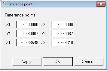
Alternatively, if you know the specific coordinates of the end points defining the rake, you can simply enter them in the X, Y, Z coordinate text boxes.
|
|
N1, N2, N3
|
If a Plane rake type is selected: the node/vector input collector (N1, N2, N3) and the Select by ID dialog can be used to select your desired nodes. However, the simplest method for selecting nodes is simply by clicking on the desired nodes in the graphics area. HyperView will automatically provide the X, Y, Z positions (coordinates) of the nodes at the time of definition. Click the expansion button  to open the Reference point dialog in order to review or change these coordinates. to open the Reference point dialog in order to review or change these coordinates.
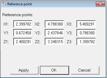
Alternatively, if you know the specific coordinates of the end points defining the rake, you can simply enter them in the X, Y, Z coordinate text boxes.
|
|
Section
|
If a Plane rake type is selected: the Section input collector and the Select by ID dialog can be used to select your desired section.
This option is only available if a section cut has been applied.
|
|
Component
|
If an Area rake type is selected: the entity input collector (Component) and the Select by ID dialog can be used to specify your desired 2D part/component. However, the easiest way to select a component is simply by clicking on the desired component in the graphics area, or in the Results browser.
|
Integration mode
|
Select the integration mode for a rake:
|
|
Downstream
|
Integration is done following the velocity field direction.
|
|
Upstream
|
Integration is done upstream, or opposite, to the velocity field direction.
|
|
Both
|
Integration is done both downstream and upstream.
|
Evenly distributed
|
Evenly distribute the seeds in an Area rake by specifying the number of rows and columns of seeds in a local system.
This option is always activated for Plane rakes.
|
Rows/Columns
|
Specify the number of rows and columns of seeds for an Area or Plane rake.
The Evenly distributed option must be activated in order to enable this option for Area rakes.
|
Number of Seeds
|
Specify the number of seeds in a Line rake.
OR
Specify the number of seeds in an Area rake (distributed on the surface of the 2D part/component), provided the Evenly distributed checkbox is not activated.
|
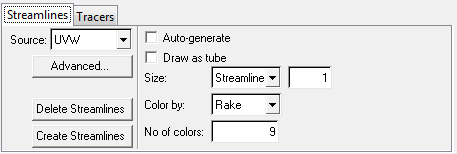
The following definition and display options are available on the Streamlines tab:
Source
|
Select the vector field to be used for streamline creation from all of the available nodal or elemental vector results (typically the velocity field).
|
Advanced
|
Opens the Advanced Options dialog, where you can change a number of parameters which control how the streamlines are generated. These settings will affect all rakes.
|
|
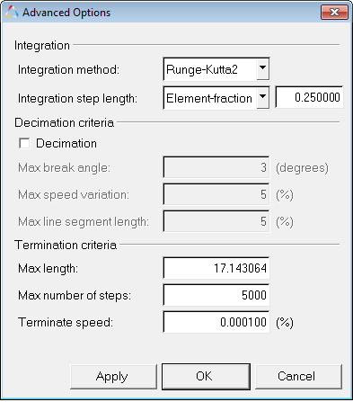
Advanced Options dialog
|
|
Integration method
|
|
|
|
|
Runge-Kutta2
|
Second order Runge-Kutta integration scheme.
|
|
Integration step length
|
|
|
|
|
Element-fraction
|
Fraction of local element size to be used as the step length for integration.
|
|
Decimation criteria
(used to reduce the memory consumption)
|
|
|
|
|
Decimation
|
Enable streamline decimation.
|
|
|
Max break angle
|
Maximum break angle (in degrees) between consecutive streamline segments.
|
|
|
Max speed variation
|
Maximum variation of speed (in percentage of the average vector field over the domain) between consecutive streamline segments.
|
|
|
Max line
segment length
|
Maximum streamline segment length in percentage of bounding box size.
|
|
Termination criteria
|
|
|
|
|
Max length
|
Maximum length of a single streamline.
|
|
|
Max number of steps
|
Maximum number of integration steps for a single streamline.
|
|
|
Terminate speed
|
Terminates the streamline integration if the speed is smaller than the percentage of the average vector (velocity) field over the domain.
|
Delete Streamlines
|
Deletes any existing streamlines for the selected rakes from the model.
|
Create Streamlines
|
Creates streamlines with the specified data for the selected rakes.
Note: It is important to note that streamlines may not always be created. For example, selecting a rake on a typical flow inlet surface and specifying Integration Mode Upstream will not produce streamlines.
|
Auto-generate streamlines
|
Automatically generate streamlines (if the rake remains at least partly in the fluid domain and the stream lines existed prior to changing the rake).
If the streamline is contoured prior to changing the rake, the contour will be automatically regenerated also.
|
Draw as tube
|
Draws the streamlines as tubes instead of lines. The streamlines will appear to have a larger diameter (for the same streamline size) when the Draw as tube option is activated.
|
Size
|
Use the drop-down menu to select one of the following options:
|
|
Streamline
|
Relative scale for the streamline thickness.
|
|
Seed
|
Specify the size of the seed nodes which are being used as the starting point for the streamline generation.
|
Color by
|
Use the drop-down menu to select one of the following options:
|
|
Seed
|
Use the number specified in the Number of colors text box to distinguish the seed streamlines.
This option is disabled if a contour is applied to the model. HyperView supports streamline contouring for nodal results only (elemental results are not supported). To remove the contour, and enable the Color by option, go to the Contour panel and click Clear Contour.
|
|
Rake
|
Each rake is displayed in one color. To change the color of a rake, right-click on the color box icon  (located in the Results browser) and select a new color. (located in the Results browser) and select a new color.
|
Number of colors
|
Number of distinct colors to use when the Color by drop-down menu is set to Seed.
|
|
Particle tracking can be used to animate streamlines of steady state CFD results. The tracers are injected into the fluid domain at the beginning of the streamlines and they travel along the streamlines.
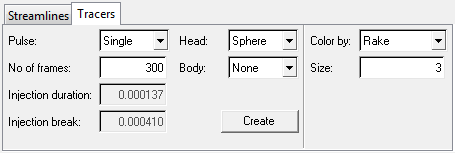
The following tracer designs, coloring options, and injection modes are available on the Tracers tab:
Pulse
|
Use the drop-down menu to select one of the following options:
|
|
Single
|
A single set of tracers is injected after all previously injected tracers have reached the end of the streamlines.
|
|
Endless
|
Tracers are continuously injected with a defined injection break (see below).
|
Number of frames
|
The number of frames used for animation. A higher value results in a slower animation, while a lower value will increase the animation speed.
|
Injection duration
|
This value controls the length of the injected line segments. For example with an ink injector, the injection duration will determine how long the ink is injected into the fluid.
This parameter is only available to be edited if the Body of the tracer is defined as Segment (see below).
|
Injection break
|
This value specifies the time difference between two injections of tracer sets. For example with an ink injector, the injection break determines the time interval in which no ink is injected.
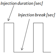
Injection duration/break for an Endless Pulse mode
This parameter is only available to be edited if the Pulse option is set to Endless (see above).
|
A tracer consists of a head and a body, both representations can be defined individually using the following options:
|
Head
|
Defines the head of the tracer. Use the drop-down menu to select one of the following options:
|
|
Sphere
|
A sphere will be placed on the tip of the tracer.
|
|
None
|
Nothing will be placed on the tip of the tracer.
|
Body
|
Defines the body of the tracer. Use the drop-down menu to select one of the following options:
|
|
Segment
|
A line will be plotted for the body of the tracer. The length of this line will be determined by the Injection duration (see above).
|
|
None
|
No line will be plotted for the body of the tracer.
|
Create
|
Creates the tracers and starts the animation for the selected rakes.
|
Color by
|
Use the drop-down menu to select one of the following options:
|
|
Seed
|
Each seed node is associated with a particular color. You can use the Number of colors option in the Streamlines tab to define the number of colors to be used. The tracers injected by a seed node are colored according to the node's associated color.
|
|
Rake
|
All tracers emitted from one rake are colored with the same color. The color of the rake can be controlled using the color box icon in the Results browser.
|
|
Injection Time
|
All tracers injected at one point in time are colored with the same color. You can use the Number of colors option in the Streamlines tab to define the number of colors to be used.
|
Size
|
This parameter controls the size of the sphere. If the Body of the tracer is defined as Segment , the thickness of the segment is controlled with this parameter.
|
Defining tracers also generates entries in the Results browser (located under the CFD Rakes folder).
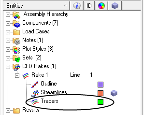
You can activate or deactivate the tracers of a particular rake by clicking on the icon next to Tracers. In addition, you can also change the color of the tracers by right-clicking on the color box (and then selecting a new color from the palette). The color selection will only take effect if the Color by option is set to Rake (on the Tracer tab).
|
| • | With Fluent 6.*: select File/Export, select EnSight Case Gold as the File Type, then select the functions that you would like to export/post-process with HyperView (for example, Static Pressure and Total Pressure), leave the default options set at Node and Binary, and click Write to export the set of EnSight files. |
| • | With Fluent 12.*: select File/Export/Solution Data…, select EnSight Case Gold as the File Type, then select the Quantities that you would like to export/post-process with HyperView (for example, Static Pressure and Total Pressure), leave the default options as Node and Binary, and click Write to export the set of EnSight files. |
| Note | By default Fluent will save the volume and boundary groups/components, therefore you do not need to select any Interior Zones. In Fluent, interior zones do not refer to the volume zones but instead refer to all of the faces (in 3D) between each pair of cells. It is very unlikely that you will ever need them, as they are used by Fluent for the solution process, and they are not needed for post-processing (as their numbers are so large that it will slow down your post-processing tasks considerably). |
|
How Do I....
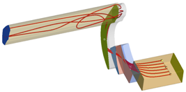
| 1. | From the Streamlines panel, click Add. Rake 1 is added to the list. |
| 2. | From the Rake type drop-down menu, select Line. |
| 3. | Define the end points of the rake: |
| - | Pick two nodes on the model. |
OR
|
|
| - | Use the node/vector input collector (N1, N2) and the Select by ID dialog to select your desired nodes. |
HyperView will automatically provide the X, Y, Z positions (coordinates) of the nodes at the time of definition.
OR
| - | If you know the specific coordinates of the end points defining the rake, you can simply enter them in the X, Y, Z coordinate text boxes. |
| Note | It is important to make sure at least a portion of the rake (at least one of the rake headers) is in the fluid field. Therefore it is highly recommended that once the nodes have been selected, that you then modify the point coordinates by giving them a small offset to make sure the rake is in the "main stream", instead of the boundary layer. This will ensure that full streamlines are created. |
You can also use the graphical manipulator to modify the rake location to ensure it is in the “main stream”, and that all requested streamlines are generated.
| 4. | Select the integration mode for the rake (Downstream, Upstream, or Both) from the Integration mode drop-down menu. |
| 5. | Enter the number of desired seeds in the Number of seeds text box. |
| 6. | From the Streamlines tab, select the vector field to be used for streamline creation (typically the velocity field) from the Source drop-down menu. |
Note - You can also click Advanced to open the dialog which allows you to change a number of parameters that control how the streamlines are generated.
| - | In addition, the Tracers tab can also be used to create and animate streamlines with particles traveling along the streamlines: |
| • | Click on the Tracers tab: |
| • | Enter your desired options for tracer designs, coloring options, and injection modes. |
| • | Click on the Create button to start the animation. |
| 7. | Enter/select your desired Display options: |
| - | Auto-generate - activate the check box to automatically generate streamlines upon release of the mouse button. |
| - | Draw as tube - active this option to draw the streamlines as tubes instead of lines. |
| - | Streamline size - enter the relative scale for the streamline thickness (the value must be a positive whole number). |
OR
Seed marker size - enter the size of the seed nodes which are being used as the starting point for the streamline generation.
| - | Color by - select Seed from the drop-down menu to use the number specified in the Number of colors text box to distinguish streamlines. |
| - | Number of colors - enter the number of distinct colors (1-14) to use when the Color by drop-down menu is set to Seed. |
| 8. | Click the Create Streamlines button to create and view the streamlines. |
|
| 1. | From the Streamlines panel, click Add. |
Rake 1 is added to the list.
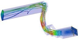
| 2. | From the Rake type drop-down menu, select Area. |
| 3. | Select the 2D part/component which will be used to define the rake: |
| - | Pick a 2D component from the model in the graphics area, or in the Results Browser. |
|
|
OR
| - | Use the entity input collector (Component) and the Select by ID dialog to select your desired entity. |
| 4. | Select the integration mode for the rake (Downstream, Upstream, or Both) from the Integration mode drop-down menu. |
| 5. | Activate the Evenly distributed check box to evenly distribute the seeds according to the number of rows and columns specified in the following steps. |
| 6. | Enter the number of desired rows of seeds in the Number of rows text box. |
| 7. | Enter the number of desired columns of seeds in the Number of columns text box. |
| 8. | From the Streamlines tab, select the vector field to be used for streamline creation (typically the velocity field) from the Source drop-down menu. |
Note - You can also click on the Advanced button to open the dialog which allows you to change a number of parameters that control how the streamlines are generated.
| - | In addition, the Tracers tab can also be used to create and animate streamlines with particles traveling along the streamlines: |
| • | Click on the Tracers tab: |
| • | Enter your desired options for tracer designs, coloring options, and injection modes. |
| • | Click on the Create button to start the animation. |
| 9. | Enter/select your desired Display options: |
| - | Auto-generate - activate the check box to automatically generate streamlines upon release of the mouse button. |
| - | Draw as tube - active this option to draw the streamlines as tubes instead of lines. |
| - | Streamline size - enter the relative scale for the streamline thickness (the value must be a positive whole number). |
OR
Seed marker size - enter the size of the seed nodes which are being used as the starting point for the streamline generation.
| - | Color by - select Seed from the drop-down menu to use the number specified in the Number of colors text box to distinguish streamlines. |
| - | Number of colors - enter the number of distinct colors (1-14) to use when the Color by drop-down menu is set to Seed. |
| 10. | Click the Create Streamlines button to create and view the streamlines. |
| Note | Area rakes without the Evenly distributed option activated cannot be manipulated. |
|
| 1. | From the Section Cut panel, apply a section cut to the model. |
| 2. | From the Streamlines panel, click Add. |
Rake 1 is added to the list.
| 3. | From the Rake type drop-down menu, select Plane. |
| 4. | Define the rake by points: |
| - | Pick three non-collinear nodes on the model. |
OR
| - | Use the node/vector input collector (N1, N2, N3) and the Select by ID dialog to select your desired nodes. |
HyperView will automatically provide the X, Y, Z positions (coordinates) of the nodes at the time of definition.
OR
| - | If you know the specific coordinates of the end points defining the rake, you can simply enter them in the X, Y, Z coordinate text boxes. |
| Note | It is important to make sure at least a portion of the rake (at least one of the rake headers) is in the fluid field. Therefore it is highly recommended that once the nodes have been selected, that you then modify the point coordinates by giving them a small offset to make sure the rake is in the ‘main stream’, instead of the boundary layer. This will ensure that full streamlines are created. |
You can also use the graphical manipulator to modify the rake location to ensure it is in the “main stream”, and that all requested streamlines are generated.
Or define the rake by section:
| - | Select the Section option from the input collector drop-down menu. |
| - | Pick a section on the model. |
OR
| - | Use the entity input collector (Section) and the Select by ID dialog to select your desired section. |
| 5. | Select the integration mode for the rake (Downstream, Upstream, or Both) from the Integration mode drop-down menu. |
| 6. | Enter the number of desired rows of seeds in the Number of rows text box. |
| 7. | Enter the number of desired columns of seeds in the Number of columns text box. |
| 8. | From the Streamlines tab, select the vector field to be used for streamline creation (typically the velocity field) from the Source drop-down menu. |
Note - You can also click on the Advanced button to open the dialog which allows you to change a number of parameters that control how the streamlines are generated.
| - | In addition, the Tracers tab can also be used to create and animate streamlines with particles traveling along the streamlines: |
| • | Click on the Tracers tab: |
| • | Enter your desired options for tracer designs, coloring options, and injection modes. |
| • | Click on the Create button to start the animation. |
| 9. | Enter/select your desired display options: |
| - | Auto-generate - activate the check box to automatically generate streamlines upon release of the mouse button. |
| - | Draw as tube - active this option to draw the streamlines as tubes instead of lines. |
| - | Streamline size - enter the relative scale for the streamline thickness (the value must be a positive whole number). |
OR
Seed marker size - enter the size of the seed nodes which are being used as the starting point for the streamline generation.
| - | Color by - select Seed from the drop-down menu to use the number specified in the Number of colors text box to distinguish streamlines. |
| - | Number of colors - enter the number of distinct colors to use (1-14) when the Color by drop-down menu is set to Seed. |
| 10. | Click the Create Streamlines button to create and view the streamlines. |
|
| 1. | From the Streamlines panel, follow the steps to create a: |
OR
OR
| 3. | Select a result type from the Result type drop-down menu. |
The contour is applied to the streamline.
| Note | HyperView supports streamline contouring for nodal results only (elemental results are currently not supported). |
|
| 1. | From the Streamlines panel, right click on the name of a rake in the Rakes list and select Rename (from the context menu). |
| 2. | Type a new name into the Rename dialog. |
OR
| 1. | From the Results Browser, right click on the name of the rake in the tree (listed under the Streamlines folder) and select Rename (from the context menu). |
| 2. | Enter a new name in the name text field and press ENTER. |
The rake is renamed.
|
| 1. | From the Streamlines panel, select a rake from the Rakes list. |
| 2. | Click the Delete button (located in the lower left corner of panel). |
OR
| 1. | From the Streamlines panel, right click on the name of a rake in the Rakes list and select Delete (from the context menu). |
The rake is removed from the list and the window.
|
See also
Contour Panel
Results Browser
Section Cut Panel
Vector Panel


![]() on the Results toolbar, or select Create > Streamlines from the Results menu.
on the Results toolbar, or select Create > Streamlines from the Results menu.
