The Beam, pipe, or truss elements option allows you to define the *SURFACE card for individual beam, pipe and truss elements. In the graphic area, these faces are displayed by special contactsurface elements. These contactsurface elements have their own normals to define the SPOS and SNEG faces. The contactsurface with normals along the underlying element normals define the SPOS faces. In contrast, the face with opposing normals defines the SNEG face.
| Note: | For 3D beam, pipe and truss elements, the SPOS and SNEG faces do not have any meaning. Therefore, these face identifiers will be ignored by the Standard.3d template. |
|
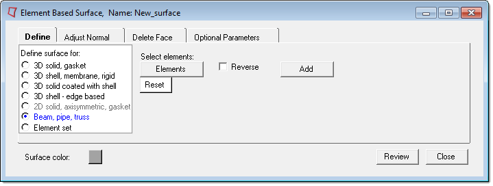
The Beam, pipe, or truss elements option has the following buttons:
Elements
|
Opens the Element Selector panel and allows you to pick the underlying beam, pipe or truss elements from the graphic area. The selected elements are highlighted. The corresponding Reset button resets the selected elements.
|
Add
|
Adds the selected elements to the current surface and creates special contactsurface elements for display. By default, SPOS faces are created. In order to create SNEG faces, activate the Reverse check box and click Add.
| Note: | You cannot add duplicate contactsurfaces for the same element in Engineering Solutions. The Add button does not check for duplicates and there is no Reject button. |
|
See Also:
3D Solid or Gasket
3D Shell, Membrane, or Rigid Elements
3D solid coated with shell
3D Shell - Edge Based
2D Solid, Axisymmetric, or Gasket Elements
Element Set
Element Based Surface: Define Tab


