|
»Click here to display Table of Contents«
|

Rotor Dynamics |

|

|

|

|
|
Rotor Dynamics |
|
|
|

|
|
»Click here to display Table of Contents«
|
Rotor Dynamics |
|
|
|
|
|
Rotor Dynamics |
|
|
|
|
Rotor dynamics is the analysis of structures containing rotating components. The dynamic behavior of such structures is influenced by the type and angular velocity of rotating components and their locations within the model. Rotor dynamics is available in OptiStruct for modal frequency response and complex eigenvalue analyses.
When a component within the structure rotates, additional forces like the gyroscopic force and circular damping force act on it. It is important to determine the effects of rotating components on the system as a whole. The natural frequencies of a system usually change, if gyroscopic forces act on the model due to a rotating component. Circulating damping forces due to rotating components can lead to system instability. These forces are a function of the frequency of rotating component. In OptiStruct, they are included in the calculation of the response of the structure of interest when required in applicable subcases.
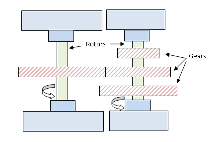
Figure 1: Illustration depicting an application of Rotor Dynamics analysis
In Figure 1, the rotating components of the structure are the shafts on which gears are mounted. The design of the rotors and their angular frequencies can affect the dynamic response of the structure. Any design will most likely lead to asymmetrical mass distribution about the rotor axes. This unbalanced mass, even if it is not significant, can result in deflection of the rotor depending on various factors. The magnitude of these deflections will be augmented when the rotating speed of the shafts equals the natural frequency of the structure (Resonance), and can lead to catastrophic failure of the system.
The Rotor Dynamics functionality is activated in OptiStruct with the use of the RGYRO subcase information entry (RGYRO = ID). This RGYRO entry references the identification number of a RGYRO bulk data entry. Related bulk data entries, RSPINR, UNBALNC, ROTORG and RSPEED are defined in the model for Rotor Dynamics. Parameters PARAM, GYROAVG, PARAM, WR3, and PARAM, WR4 are also used.
A rotor is a structure that rotates about its own axis at a specific angular velocity. If a lateral force is applied to the rotor, it will deform in the lateral direction. This deformation is dependent on various factors, such as, magnitude of the applied force, rotor material properties, stator stiffness, and damping within the system. Due to rotor rotation, the deformed rotor will also whirl about an axis.
The whirling speed can either be the same as rotor speed or it can be different from it. The type of analysis performed if the whirling speed and the rotor speed match is known as synchronous analysis. If the speeds do not match, then asynchronous analysis is used to determine the dynamic response of the model. In OptiStruct, the RGYRO bulk data entry can be used to select synchronous/asynchronous analysis.
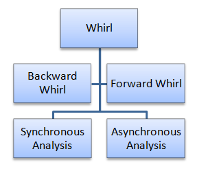
Figure 2: Types of Whirl and the two analysis types that are dependent on the angular frequency of a rotor.
The type of whirl depends on the spin direction of a rotor. If the rotor spin direction is the same as that of its whirl direction, then it is termed as forward whirl. If the rotor spin direction is opposite to the whirl direction, it is termed as backward whirl. In complex eigenvalue analysis, you can determine and differentiate between the modes of a structure undergoing backward whirl and forward whirl.
OptiStruct supports the Rotor dynamics functionality in the following solution sequences:
The response of a structure with rotating components to a specified external excitation can be determined using the rotor dynamics functionality in frequency response analysis.
Asynchronous analysis (RGYRO = ASYNC)
If ASYNC is specified in the RGYRO bulk data entry, the rotors within the structure have user-defined spin rates. The excitation frequency (FREQi entries) is independent of the reference rotor speed defined in the RGYRO entry.
Synchronous analysis (RGYRO = SYNC)
If SYNC is specified in the RGYRO bulk data entry, the reference rotor spin rate is equal to (or synchronous with) the excitation frequency. The reference rotor speed is not input via the RGYRO entry and the FREQi entry values are used in this analysis.
The eigenvalues and critical speeds of a structure with rotating components can be determined using the rotor dynamics functionality in complex eigenvalue analysis.
Asynchronous analysis (RGYRO = ASYNC)
If ASYNC is specified in the RGYRO bulk data entry, the rotors within the structure have user-defined spin rates via the RSPEED entry and the Campbell Diagram can be plotted to find the critical speeds. Additionally, since the calculated eigenvalues are complex, you can determine unstable modes by studying the real parts of the calculated eigenvalues. If the real part of a complex eigenvalue is positive, then the corresponding system mode is unstable.
Synchronous analysis (RGYRO = SYNC)
If SYNC is specified in the RGYRO bulk data entry, only the critical speeds are calculated as the rotor speeds are equal to the whirl frequencies. These critical speeds can lead to structural resonance and the design should be modified to change its whirl frequencies or the operating rotor spin rate should be limited to avoid reaching the critical speeds.
|
Asynchronous analysis is activated using the RGYRO=ASYNC option. Frequency response analysis in rotor dynamics involves defining the excitation either as an external varying load as a function of frequency or as a rotor unbalance via the UNBALNC entry (or as a force that simulates the effect of the rotor unbalance). Asynchronous frequency response analysis in OptiStruct is designed for an external varying force at a specific set of frequencies. The following equation implements the external loading functionality in OptiStruct. The rotor speeds should be specified by you for Asynchronous frequency response analysis.
The response of a system with rotating components to an external load in the frequency domain is calculated based on the above equation.
Synchronous analysis is activated using the RGYRO=SYNC option. Frequency response analysis in rotor dynamics involves defining the excitation either as an external varying load as a function of frequency or as a rotor unbalance via the UNBALNC entry (or as a force that simulates the effect of the rotor unbalance). Synchronous frequency response analysis in OptiStruct is designed to calculate the response of a system with a rotor unbalance. The following equation implements the rotor unbalance functionality in OptiStruct. The rotor speeds are determined from the FREQi entries for Synchronous frequency response analysis.
The response of a system with rotating components to a rotor imbalance which is considered as a force acting in the frequency domain is calculated based on the above equation.
Parameters PARAM, WR3, PARAM, WR4, and PARAM, WRH can be used to avoid frequency dependent calculation of the rotor damping and circulation terms in systems with multiple rotors. The frequency values in the circulation damping terms are replaced with the values of the parameters as shown in the equation below. PARAM, GYROAVG should be set to -1 to be able to bypass frequency dependent look-up and use the WR3, WR4, and WRH values.
Parameters PARAM, WR3, PARAM, WR4 and PARAM, WRH can be used to avoid frequency dependent calculation of the rotor damping and circulation terms in systems with multiple rotors. The rotor speeds can be calculated as a linear function of the reference rotor spin rate (see description of terms below). The reference rotor spin rate values in the circulation damping terms are replaced with the values of the parameters as shown in the equation below. PARAM, GYROAVG should be set to -1 to be able to bypass frequency dependent look-up and use the WR3, WR4, and WRH values.
The eigenvalues and critical speeds of a structure with rotating components can be determined using the rotor dynamics functionality in complex eigenvalue analysis. In asynchronous analysis the critical speeds can also be determined by plotting the Campbell diagram for frequencies specified using the RSPEED entry. The parameters PARAM, WR3, PARAM, WR4, and PARAM, WRH can be used to replace the values of WR3, WR4, and WRH in the equation below.
Only the rotor speeds are required to perform the synchronous complex eigenvalue analysis as the whirl frequencies are equal to the reference rotor spin rates. Only the critical speeds are output as a result of this analysis. The parameters PARAM, WR3, PARAM, WR4, and PARAM, WRH can be used to replace the values of WR3, WR4, and WRH in the equation below.
Where,![]() is the reference rotor spin rate
is the reference rotor spin rate
![]() is the spin rate of rotor “j” as a function of the reference rotor spin rate.
is the spin rate of rotor “j” as a function of the reference rotor spin rate. ![]() can be determined for each excitation frequency or it can be calculated as a linear function of the reference rotor spin rate:
can be determined for each excitation frequency or it can be calculated as a linear function of the reference rotor spin rate:
![]()
Where,
aj and ![]() j are scaling factors calculated from the relative spin rates defined in the RSPINR bulk data entry.
j are scaling factors calculated from the relative spin rates defined in the RSPINR bulk data entry.
[M] is the structural mass
![]() is the viscous damping of the support
is the viscous damping of the support
![]() is the rotor viscous damping
is the rotor viscous damping
![]() is the rotor hybrid viscous damping
is the rotor hybrid viscous damping
![]() is the rotor mass
is the rotor mass
![]() is the rotor stiffness
is the rotor stiffness
![]() is the rotor material damping
is the rotor material damping
![]() is the rotor hybrid material damping
is the rotor hybrid material damping
![]() is the circulation, due to rotor viscous damping
is the circulation, due to rotor viscous damping
![]() is the circulation due to rotor hybrid viscous damping
is the circulation due to rotor hybrid viscous damping
![]() is the circulation, due to rotor mass
is the circulation, due to rotor mass
![]() is the circulation, due to rotor structural stiffness
is the circulation, due to rotor structural stiffness
![]() is the circulation, due to rotor material damping
is the circulation, due to rotor material damping
![]() is the circulation, due to rotor hybrid material damping
is the circulation, due to rotor hybrid material damping
![]() is the stiffness of the support
is the stiffness of the support
![]() is the material damping of the support
is the material damping of the support
N is the number of rotors in the model
![]() is the displacement as a function of frequency
is the displacement as a function of frequency
![]() is the displacement as a function of reference rotor spin rate
is the displacement as a function of reference rotor spin rate
![]() is the external excitation as a function of frequency
is the external excitation as a function of frequency
![]() is the unbalanced load as a function of reference rotor spin rate (via DAREA or UNBALNC entries)
is the unbalanced load as a function of reference rotor spin rate (via DAREA or UNBALNC entries)
G is the structural damping value of the support defined using PARAM, G
GR is the structural damping value of the rotor defined using PARAM, G
![]() and
and ![]() are used to define the Rayleigh viscous damping, as follows:
are used to define the Rayleigh viscous damping, as follows:
![]() and
and ![]()
![]() and
and ![]() are used to define the scale factors of the linear fit (between SPDLOW and SPDHIGH on the ROTORG entry) of the rotor speed to the reference rotor speed.
are used to define the scale factors of the linear fit (between SPDLOW and SPDHIGH on the ROTORG entry) of the rotor speed to the reference rotor speed.
WR3 and WR4 are defined by the parameters PARAM, WR3 and PARAM, WR4, respectively.
WR3, WR4, and WRH are defined by the parameters PARAM, WR3, PARAM, WR4, and PARAM, WRH. These parameters allow you to bypass frequency-dependent looping by specifying the equivalent “average” excitation frequencies when PARAM, GYROAVG, -1 is specified.
Rotor structural damping factor (GR) can be incorporated as either equivalent viscous damping or structural damping depending on the solution sequence.
or
![]()
Where, WR3 is a parameter defined by PARAM, WR3 and GR is defined as a field on the RSPINR bulk data entry.
The selection depends on the following factors:
| • | Modal frequency response or Complex eigenvalue analysis. |
| • | Synchronous or Asynchronous solutions. |
| • | Value of PARAM, GYROAVG. |
The general form of a circulation damping term is given as:
Where, D is the regular damping matrix and T is a skew-symmetric rotation matrix defined as follows in the rotor coordinate system:
This 6x6 T matrix is repeated for each grid along the rotation axis of the rotor. The individual T matrices are added in the diagonal of the global skew-symmetric matrix.
![]() is the gyroscopic matrix defined in a rotor coordinate system as follows:
is the gyroscopic matrix defined in a rotor coordinate system as follows:
The OptiStruct rotor dynamics feature currently supports only 1D rotors. Rotor shafts modeled with 1D elements like CBEAM, CBAR, or CBUSH only can be used. CONM1 or CONM2 entries should be used to define the mass and inertia of the rotors. Grid points are necessary for the definition of mass and inertia via CONM1 or CONM2. All grid points that belong to rotors should be listed in the ROTORG entries and only grids listed in the ROTORG entries are included in the calculation of gyroscopic terms. The Ixx fields on the CONM2 entry should contain meaningful values as only the inertia about the local X, Y, or Z axes plays a role in the gyroscopic forces (Supported Solution Sequences section). If CONM1 entries are used, the Mxy mass values should be specified such that the moments of inertia about the local X, Y, or Z axes are meaningful.
The rotor should be detached from the rest of the structure. Only rigid elements (RBEi) can be used to attach rotors to the ground or to flexible bearings. If any connection exists between the rotor and other parts of the structure using elements other than RBEi, then the program will error out.
Rotor dynamics analysis in OptiStruct is performed based on assumption that the rotor is symmetric. Therefore, the rotor model is required to be symmetric about the rotation axis. The implementation is based on equations of motion formulated in a fixed reference frame. Asymmetric rotors in a rotating reference frame is planned to be implemented in future versions of OptiStruct.
During synchronous analysis, the calculations are performed with respect to the reference rotor. In synchronous frequency response analysis, the reference rotor is rotating at the frequency of the unbalanced load and in synchronous complex eigenvalue analysis, the reference rotor is rotating at the whirl frequency of the system. The interpretation of results in a multiple rotor system should always be done with respect to the reference rotor. Any deduction of results from the behavior of rotors other than the reference rotor will be inaccurate and can lead to incorrect results. If the behavior of a rotor other than the reference rotor is to be studied, a different analysis should be run with the rotor of interest as the reference rotor.
The critical speeds of a rotating structure should be calculated and the design parameters can then be altered if necessary to restrict the operating speeds of the structure from attaining those resonant speeds. The structure may undergo excessive amplitude and phase changes if its operating speeds reach critical speeds. The calculation of critical speeds in OptiStruct can be undertaken in two ways:
| 1. | Synchronous Complex Eigenvalue Analysis |
The RGYRO=SYNC option in Complex Eigenvalue Analysis can be used to determine the exact critical speeds of the rotating structure. During a synchronous analysis, the rotor speed is equal to the whirl frequency of the structure, which by definition, are the critical speeds of the structure that should be avoided during its operation.

Figure 3: An example Campbell Diagram to calculate the critical speeds.
| 2. | Asynchronous Complex Eigenvalue Analysis |
The RGYRO=ASYNC option and the RSPEED bulk data entry in Complex Eigenvalue Analysis can be used to determine the whirl frequencies (backward whirl and forward whirl) of the structure. These Whirl frequencies can be calculated for a sequence of rotor spin rates. Forward Whirl and Backward Whirl frequencies can then be plotted against the range of rotor spin rates (Figure 3). The critical speeds can be calculated by superimposing the “Rotor Spin Rate = Whirl Frequencies” line on the plot. The points of intersection are the critical speeds.
|
Rotors in frequency response and complex eigenvalue solutions can be replaced using superelements. Superelements can be attached to the grids that define the rotor in the ROTORG bulk data entry. Craig-Bampton Nodal Formulation (CBN) or Guyan Reduction (GUYAN) can be specified on the METHOD field in the CMSMETH bulk data entry to generate the superelements. The superelement replaces the beam elements used to model the rotor. The ASET grid points should correspond to the GRIDi points specified on the ROTORG bulk data entry. The interface grid points of the superelement used to model the rotor should be exactly the same grid points defined on the ROTORG entry. The General Modal Formulation (GM method) cannot be used to generate superelements for Rotor dynamics.
| Note: | The Inertia (I66) and Equivalent Mass information pertaining to the Rotor superelement at the ASET connection points is printed to the .out file. This inertia information can subsequently be utilized to aid in replacing the Rotor Superelement with equivalent CONM2 concentrated mass elements. |